
Electrical energy and distribution system

a technology of electric energy and distribution system, applied in the direction of electric power transfer ac network, single network parallel feeding arrangement, constant-current supply dc circuit, etc., can solve the problems of only economically viable and relatively expensive schemes, and achieve the effect of increasing system reliability and availability, enabling easy maintenance and troubleshooting

Active Publication Date: 2010-12-23
RENERGYX
View PDF34 Cites 28 Cited by
  • Summary
  • Abstract
  • Description
  • Claims
  • Application Information

AI Technical Summary

Benefits of technology

[0011]By connecting multiple electrical generators in a series DC loop, the invention is capable of delivering high voltage DC. The use of high voltage reduces transmission loss due to the corresponding low current. Also the absence of reactive (inductance as well as capacitance) effects associated with AC power distribution systems improves the balance of the delivered power.
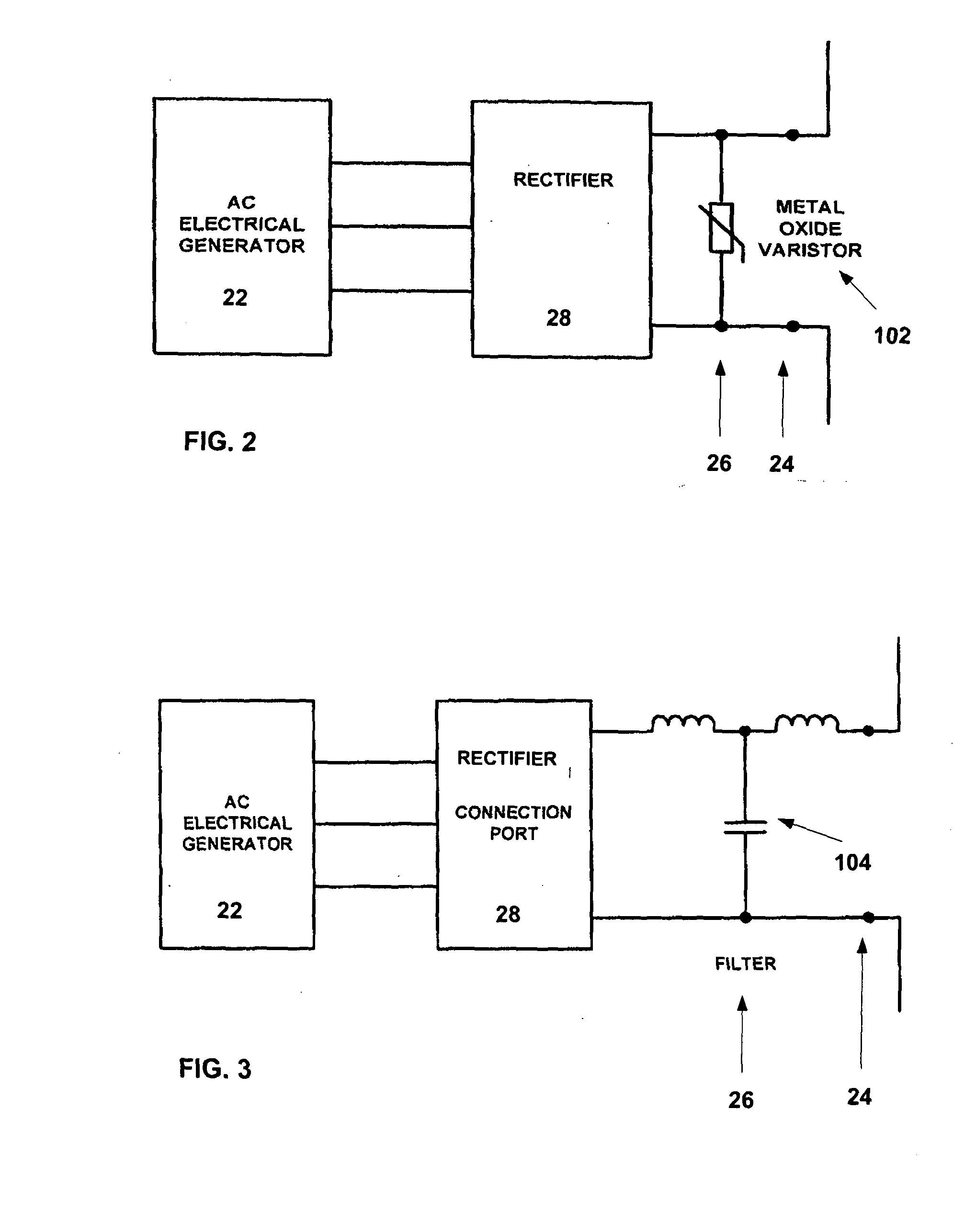
[0014]The electricity conditioning circuitry on the supply side may involve a switching regulator in boost mode. Other switching regulators such as a flyback regulator, a buck regulator and a bridge regulator may be used. The electricity conditioning circuitry allows variation in the DC loop voltage by adjustment and synchronisation of the supply side connection ports.
[0026]The system allows electrical generators and loads to be connected and disconnected without disrupting operation of other parts of the system. Flexibility to connect and disconnect generators increases system reliability and availability while enabling easy maintenance and troubleshooting. New generators and loads may also be added easily.

Problems solved by technology

These schemes are relatively expensive and are only economically viable on large scale electrical power systems.

Method used


Image

  • Electrical energy and distribution system
  • Electrical energy and distribution system
  • Electrical energy and distribution system

Examples


Embodiment Construction

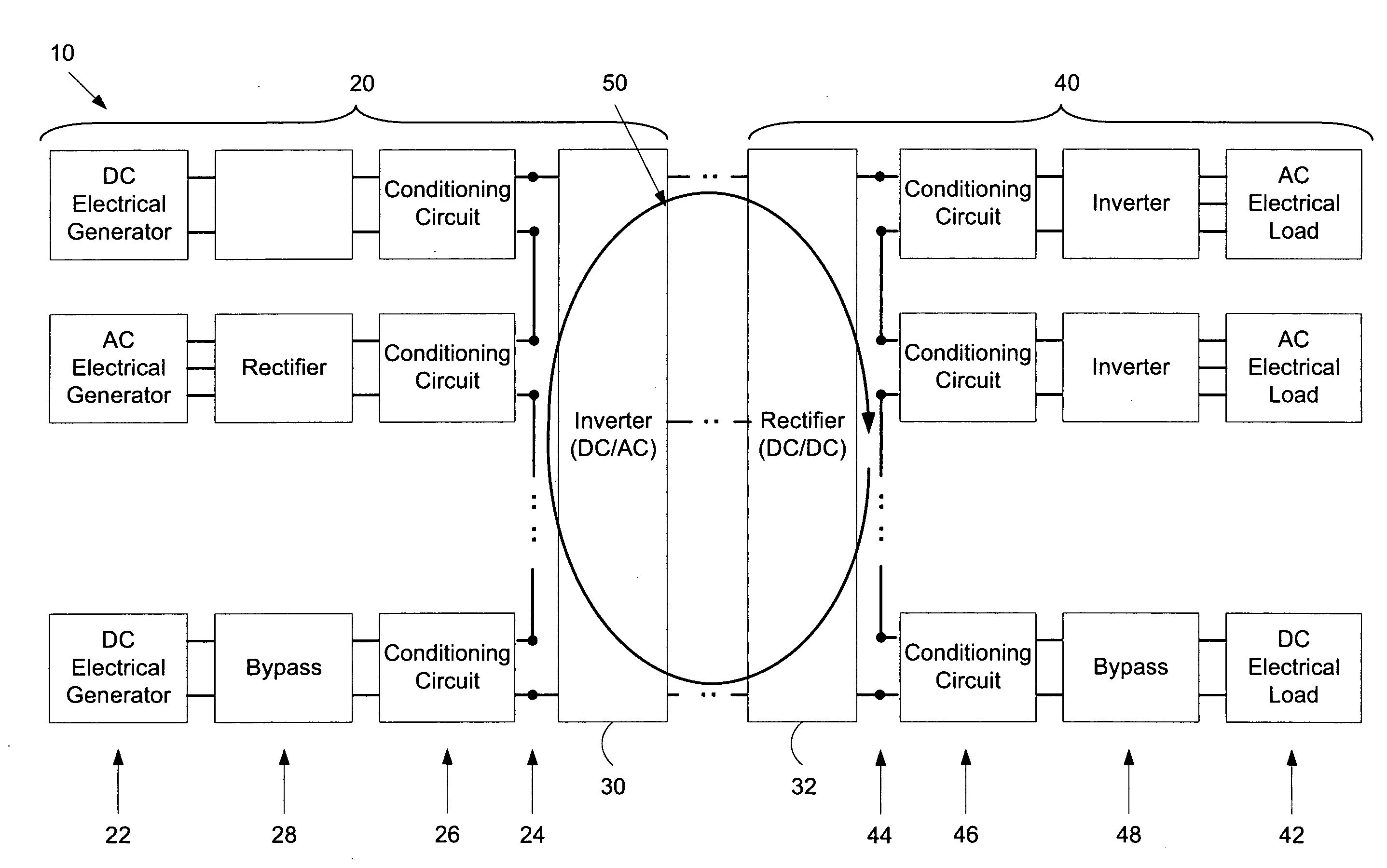
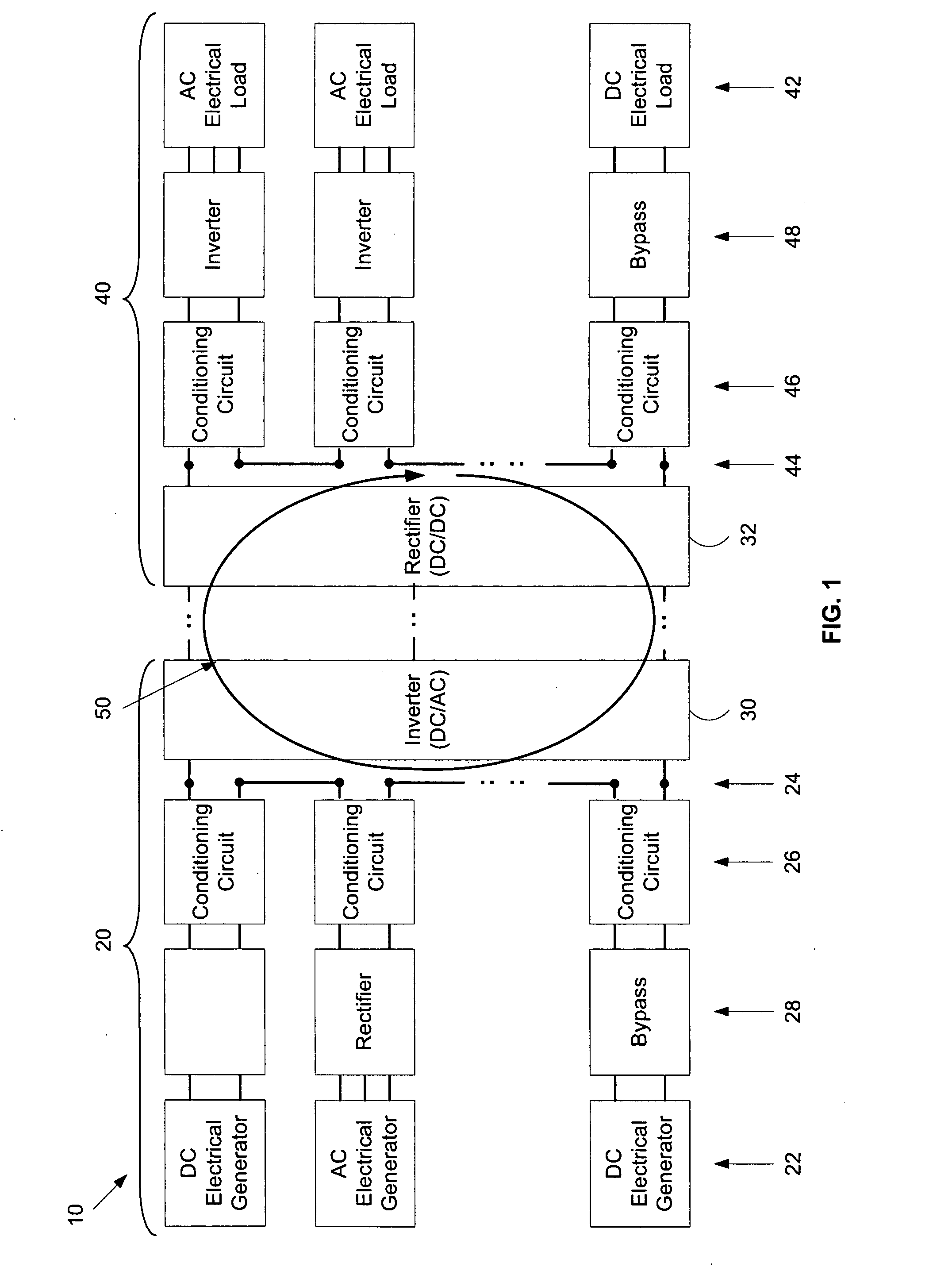
[0035]Referring first to FIG. 1, the electrical system 10 comprises a supply side 20 where, generally, multiple electrical energy generators 22 are connected via connection ports 24, involving conditioning circuits 26 and possibly additional conditioning circuitry 28, into a single DC electrical energy source. This energy source is supplied to a common inverter system 30 to convert it to AC for transmission on over a power grid. A rectifier 32 takes the AC power from the grid and delivers it to AC and DC loads. On the delivery side 40 energy is delivered to multiple loads 42 via connections ports 44 involving conditioning circuits 46 and other conditioning circuitry 48.

[0036]In this way the electrical energy generators 22 are connected in a series DC loop 50. Electrical circuit theory dictates that the current in each part of the series DC loop 50 is the same but the voltage developed by each generator is added together. The power delivered is therefore the product of the total volt...


PUM


Abstract

This invention concerns an electrical energy supply and distribution system. The system is able to handle both large centralised electricity generation plants, as well secondary energy sources which are becoming increasingly important. These sources may or may not be connected to deliver electrical energy to a 50 Hz AC power distribution grid. The system comprises a supply side where multiple electrical energy generators are connected via connections ports, involving conditioning circuitry, into a single DC electrical energy source. This energy source may be supplied to a common inverter system to convert it to AC for transmission on over a power grid. A rectifier may take the AC power from the grid and delivers it to loads. Whether an AC grid in involved or not, on the delivery side energy is delivered to multiple loads via connection ports involving conditioning circuitry. Any of the generators or loads may be taken offline or connected back into the system at will.

Description

TECHNICAL FIELD[0001]This invention concerns an electrical energy supply and distribution system.BACKGROUND ART[0002]Industrialised countries are heavily dependent on large centralised electricity generation plants to produce power. For example, 80% of the electricity generated in Australia is produced by coal power plants. These power plants are usually built away from the cities where the power is consumed.[0003]In addition, secondary energy sources are becoming increasingly important. Common renewable energy sources include photovoltaic (PV) solar cells, wind turbine generators, wave turbine generators and tidal turbine generators. These sources can be connected to deliver electrical energy to the standard 50 Hz AC power distribution grid by means of AC inverter schemes designed to synchronize with the power grid.[0004]Because the secondary sources deliver fluctuating amounts of energy, connection to the power grid invariably requires some energy storage, with an energy delivery ...

Claims


Application Information

Patent Timeline
IPC IPC(8): H02J3/38
CPCH02J3/36H02M2001/0074H02M2001/0077H02M2001/008Y02E60/60Y02E10/763H02J3/382H02J3/383H02J3/386Y02E10/563H02J3/381H02J1/04H02J2300/40H02J2300/10H02J2300/28H02J2300/20H02J2300/24Y02E10/56Y02E10/76H02M1/0074H02M1/0077H02M1/008
Inventor HARRISON, CRAIG WILLIAM
Owner RENERGYX
Learn More