Imaging array data acquisition system and use thereof

a data acquisition and imaging array technology, applied in the field of dynamic imaging system, can solve the problems of physical cumbersomeness, various distortions, backburner status, and disappointment in fluoroscopic applications, and achieve the effects of reducing instrumentation noise, reducing instrumentation noise, and reducing the size of pixels

Inactive Publication Date: 2011-01-13
THE RES FOUND OF STATE UNIV OF NEW YORK
View PDF11 Cites 19 Cited by
  • Summary
  • Abstract
  • Description
  • Claims
  • Application Information

AI Technical Summary

Benefits of technology

[0019]The imaging system, computer readable medium, and method of the present invention exhibit clear advantages over flat-panel devices and x-ray image intensifiers of the prior art. These advantages include higher spatial resolution with smaller pixels, lower instrumentation noise hence better operation at lower exposure, huge dynamic range due to adjustable on-chip gain, no lag, no ghosting, and scalable production based on existing solid state technology. The imaging system, computer readable medium, and method of the present invention have wide-reaching application to substantially improving the accuracy of both diagnosis and minimally invasive treatment of cardiovascular disease, stroke, and cancer, the three leading causes of death and disability. Both improved dynamic temporal resolution and much higher spatial resolution imaging than are presently available as well as new modalities of region of interest fluoroscopy, angiography, and computed tomography will be enabled at substantially lower integral patient radiation doses. Improved diagnostic imaging procedures and more accurate image guided minimally invasive treatments have positive implications not only toward improving health care but also toward reducing health care costs.

Problems solved by technology

They are physically cumbersome and suffer from various distortions as a result of the signal amplification process, including susceptibility to the Earth's magnetic field.
Direct FPDs, where the x-ray energy is converted directly into hole-electron pairs, were also tried before being relegated to back-burner status due to severe technical problems.
Although FPDs are successfully replacing film-screen image receptors for static imaging where higher exposures per frame are needed, they have been somewhat disappointing for fluoroscopic applications where about 1 / 100th the x-ray exposure per frame is typically used and for angiography where spatial resolution improvement is not apparent.
Preliminary research on schemes for providing increased gain at each pixel using additional amplifiers or exotic avalanche devices, or new direct photo-conductors, have been reported at scientific meetings for years; however, no practical solutions have been developed.
Thus, in FPDs, physicians are expected to accept degraded fluoroscopy in exchange for some improvement in radiographic or angiographic (higher exposure) images; however, these improvements do not include better spatial resolution.
Additionally, FPD developers have had to cope with unexpectedly difficult problems of lag and ghosting encountered during rapid sequence imaging where residual charge from previous images is superimposed on the current image being acquired, a problem that is not characteristic of XII systems where video cameras based on CCD image sensors do not exhibit such lag or ghosting.
Such CCD-based detectors, however, are not suitable for dynamic imaging.

Method used


Image

  • Imaging array data acquisition system and use thereof
  • Imaging array data acquisition system and use thereof
  • Imaging array data acquisition system and use thereof

Examples


example 1

Prototype Solid State X-Ray Imaged Intensifier (SSXII)

[0077]A prototype EMCCD camera system (Photonic Sciences Limited modified CoolView camera, East Sussex, UK) modified with a fiber-optic plate (FOP) window for the 1004×1002 TC285SPD chip that was used was created as described in Kuhls-Gilcrist et al., “The Solid-State X-ray Image Intensifier (SSXII): An EMCCD-Based X-ray Detector,”Proc. Soc. Photo. Opt. Instrum. Eng. Medical Imaging 6913-19 (2008), which is hereby incorporated by reference in its entirety. The EMCCD camera was delivered with a thin removable GOS phosphor and a few random small white spots were noticed on the images, which subsequently were found to be direct x-ray absorption in the EMCCD. The GOS was subsequently replaced with a 350 μm thick CsI(Tl) FOP module and the resulting images were free of these artifacts. The CsI module was optically coupled directly to the EMCCD FOP and images were obtained that exceeded expectations. For example, FIG. 6 demonstrates th...

example 2

System Construction for a Single Modular Device

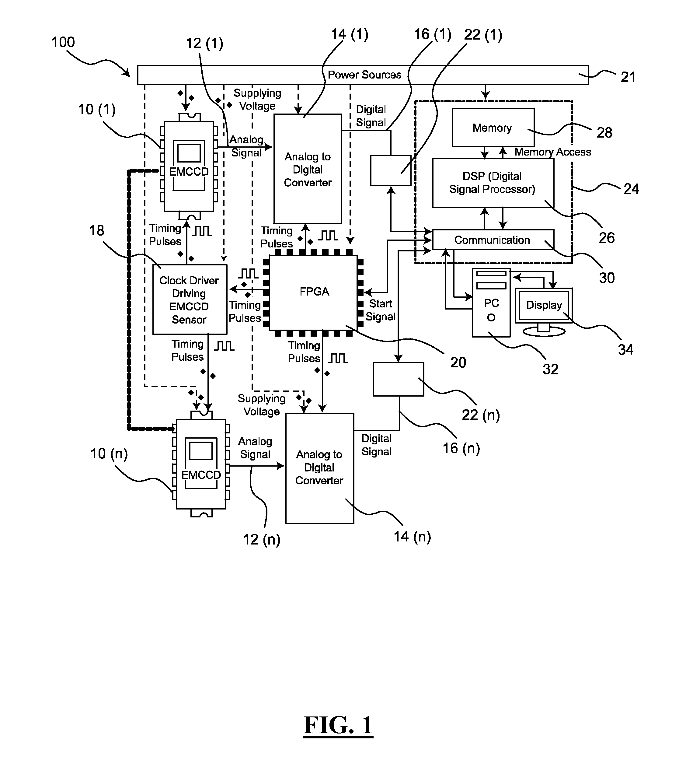
[0081]To have the most flexibility in building an optimized imaging system, it must be possible to control the design aspects at the component and system level. Thus, construction of a prototype system from components that could be extrapolated to the final system was initiated. A modular device based on a CCD chip, the Texas Instruments TC237B, that has similar architecture to readily available EMCCD chips, the TI TC247SPD and the TC253SPD, was created. The TC253SPD is a frame transfer chip nominally with 680×500 pixels of which 658H×496V are active with 7.4 μm square pixels while the TC247SPD has 10 μm pixels. The TC285SPD EMCCD has 1004×1002 pixels. All have similar clocking pulse specifications; however, the TC247SPD, TC253SPD, and TC285SPD have additional multiplying elements and hence additional pins for the control voltage that determines the “charge carrier multiplication” or gain as well as for the optional Peltier cooler that ...

example 3

2×2 SSXII Array

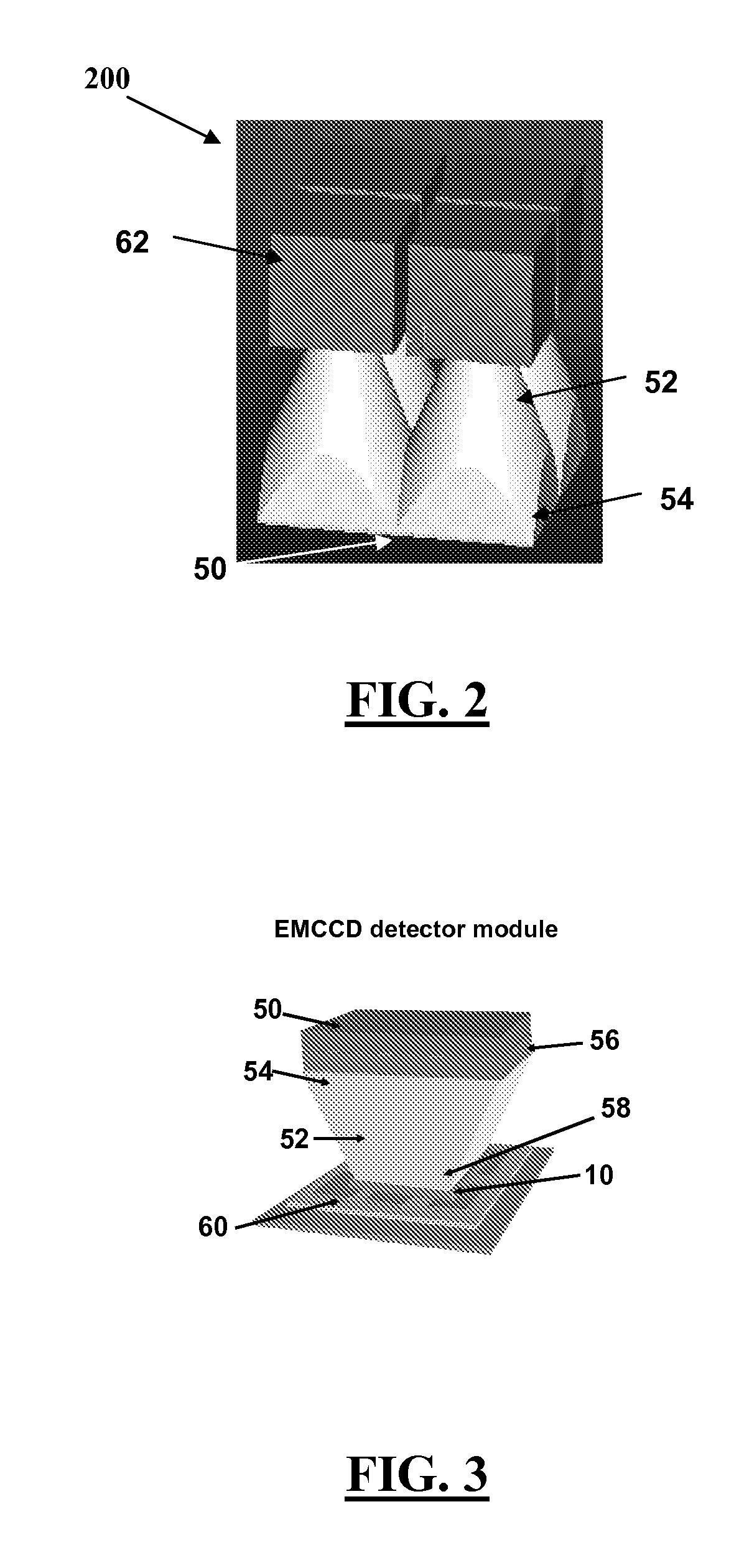
[0083]To achieve larger fields of view, an array of modular devices as indicated in FIG. 2 will be designed such that the phosphor layer is contiguous, just as in all current XII and FPD imagers. The rationale for the 2×2 array using Photonic Science Ltd. (East Sussex, UK) or similar cameras is that the PSL camera was shown to work well in Example 1. A National Instruments (NI) 1429 frame grabber board, which can achieve 30 fps for 1024×1024 matrix images with no binning, will be used (the NI 1430 has two CameraLink inputs per board) together with a high speed PC to achieve 30 fps acquisition rates for the SSXII 2×2 array.

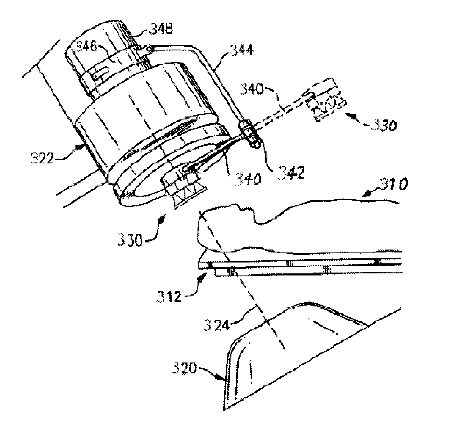
[0084]To build the 2×2 SSXII array, the four cameras will be mounted onto an array of FOTs. One way to assure that there is the smallest separation or image area loss between modular devices is to pre-assemble the FOTs into an array by bonding them together after the sides are ground but prior to grinding the input surface to enable either plating of...


PUM

PropertyMeasurementUnit
sizesaaaaaaaaaa
thickaaaaaaaaaa
lengthaaaaaaaaaa

Abstract

The present invention relates to an imaging system, computer readable medium, and method for dynamic imaging of an object to be examined. The imaging system includes detection array comprising an array of modular devices positioned such that one or more modular devices are capable of simultaneously receiving at least a portion of a first output signal from an emission source of an object to be imaged, each of said modular devices comprising a detector device, wherein each of the modular devices in the array is capable of converting at least a portion of the first output signal to a second output readout. The imaging system further includes a processing unit operatively coupled to the detection array and capable of processing the second output readouts of one or more of the modular devices, wherein said processing comprises adjusting the relationship between any combination of a second output collection rate for each active modular device, a second output readout rate, a frame rate for each active modular device, binning factor, and a number of active modular devices determining an image field of view to maintain a total output data acquisition rate below a maximum data acquisition rate of the processing unit and to obtain an image of the object.

Description

[0001]This application claims the benefit of U.S. Provisional Patent Application Ser. No. 61 / 028,768, filed Feb. 14, 2008, which is hereby incorporated by reference in its entirety.FIELD OF THE INVENTION[0002]The present invention relates to a dynamic imaging system (i.e., for imaging moving objects), computer readable medium, and method for dynamic imaging.BACKGROUND OF THE INVENTION[0003]With the onset of improved, patient-specific treatments for vascular disease and advancing diagnostic techniques, there is an increasing need for high-quality, high resolution images obtainable in real time (Rudin et al., “Endovascular Image-Guided Interventions (EIGIs),”Med. Phys. 35(1):301-309 (2008)). Current state-of-the-art medical x-ray image intensifiers (XII), the vacuum bottle electron multiplier imagers, that have dominated the real-time radiographic imaging field for over fifty years, have inherent limitations (Rudin et al., “Accurate Characterization of Image Intensifier Distortion,”Me...

Claims


Application Information

Patent Timeline
Patent Type & Authority Applications(United States)
IPC IPC(8): G01N23/04H04N7/18
CPCH04N3/1593H04N5/3725H04N5/32H04N25/41H04N25/72
Inventor RUDIN, STEPHEN
Owner THE RES FOUND OF STATE UNIV OF NEW YORK
Why Eureka
Try Eureka