Catalyst Layer for Fuel Cell Membrane Electrode Assembly, Fuel Cell Membrane Electrode Assembly Using the Catalyst Layer, Fuel Cell, and Method for Producing the Catalyst Layer

a fuel cell membrane electrode and catalyst layer technology, applied in the direction of cell components, physical/chemical process catalysts, sustainable manufacturing/processing, etc., can solve the problems of insufficient discharge of generated water from a cathode, insufficient release of generated gas from an anode, and the catalyst layer used for conventional fuel cell membrane electrodes suffers, etc., to achieve better electron conductivity, improve power generation performance, and improve structural stability

Active Publication Date: 2011-01-13
ONED MATERIAL INC
View PDF30 Cites 48 Cited by
  • Summary
  • Abstract
  • Description
  • Claims
  • Application Information

AI Technical Summary

Benefits of technology

[0015]Initially, conventional catalyst layers include only primary pores, whereas the catalyst layer of the present invention includes both primary pores and secondary pores. Accordingly, the catalyst layer of the present invention has better material diffusibility than conventional catalyst layers.
[0017]Therefore, although densely packing agglomerates in the catalyst layer or densely packing catalysts in the agglomerates in order to make the catalyst layer of the present invention compact will result in smaller primary pores and secondary pores, catalysts contact more densely with each other at portions where the catalysts contact with each other at a plurality of contact points. This prevents drop of power generation performance.
[0018]As described above, the catalyst layer of the present invention can overcome a trade-off relation between the request for making the catalyst layer compact and the request for high power generation performance necessary for a fuel cell.
[0020]Further, since agglomerates and catalysts consisting the catalyst layer of the present invention can be formed without using a nonconductive material such as diamond, the catalyst layer of the present invention exhibits better power generation performance compared with known catalyst layers that include nonconductive diamond particles.
[0021]Further, since the catalyst layer of the present invention has such a structure that catalysts contact with each other at a plurality of contact points, the catalyst layer of the present invention has better electron conductivity and better structural stability compared with known structures in which a carbon nano-horn contacts with the central nucleus of a carbon nano-horn aggregate only at one point.

Problems solved by technology

However, catalyst layers used for conventional fuel cell membrane electrodes suffer the following problems.
Extracting a high current using the catalyst layer with a lower material diffusibility will lead to insufficient release of generated gas from an anode and insufficient discharge of generated water from a cathode and to insufficient feeding of fuel and air.
This is likely to drop power generation performance of a fuel cell.
Although the compact (i.e. thin) catalyst layer has advantage in terms of proton conduction in the catalyst layer, since the length of proton diffusion is short, it is difficult to keep pore size and porosity large, when the catalyst layer is compact.
Since the catalyst layer has nonconductive diamond particles in aegagropila-linnaei-shaped carbons, a fuel cell catalyst electrode suffers low electronic conductivity, resulting in lower power generation performance of a fuel cell.
Consequently, it is highly likely that contact between carbon nano-horns get broken.
This is highly likely to result in drop of electronic conductivity (power generation performance).
Further, such structure is unstable as a structure of a catalyst layer.

Method used


Image

  • Catalyst Layer for Fuel Cell Membrane Electrode Assembly, Fuel Cell Membrane Electrode Assembly Using the Catalyst Layer, Fuel Cell, and Method for Producing the Catalyst Layer
  • Catalyst Layer for Fuel Cell Membrane Electrode Assembly, Fuel Cell Membrane Electrode Assembly Using the Catalyst Layer, Fuel Cell, and Method for Producing the Catalyst Layer
  • Catalyst Layer for Fuel Cell Membrane Electrode Assembly, Fuel Cell Membrane Electrode Assembly Using the Catalyst Layer, Fuel Cell, and Method for Producing the Catalyst Layer

Examples


example 1

2. Example 1

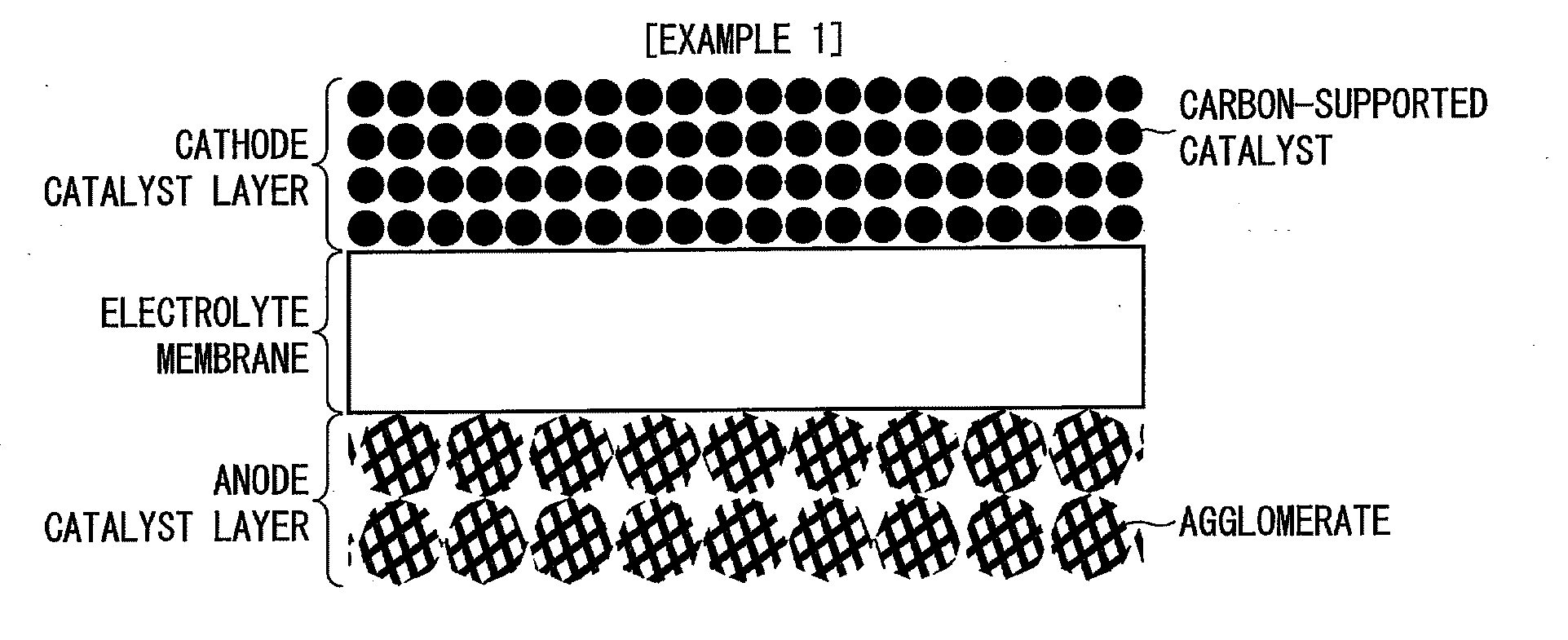
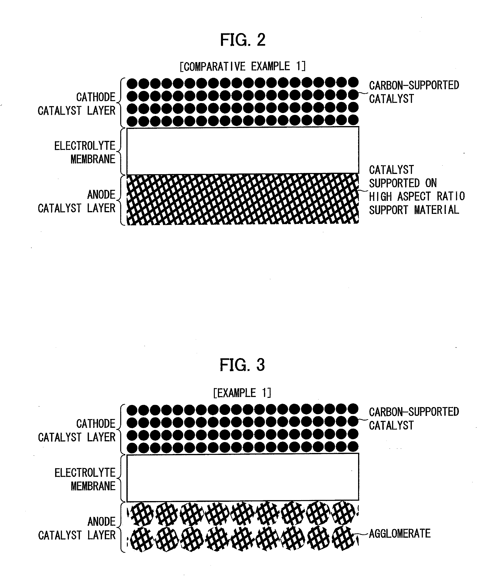
[0133]FIG. 3 is a drawing showing a fuel cell membrane electrode assembly in accordance with an example (Example 1) in which the catalyst layer of the present invention was used as an anode catalyst layer.

[0134]An anode catalyst layer in Example 1 was formed by spraying, to an electrolyte membrane, a catalyst dispersion liquid prepared by ultrasonicating a nanowire-supported PtRu-catalyst, a Nafion® solution, 2-propanol, and water.

[0135]The cathode catalyst layer in Example 1 was the same as that in Comparative Example 1 and an explanation thereof is omitted here.

3. Results of Analyses

[0136]SEM (scanning electron microscope) images of the catalyst layers of Example 1 and Comparative Example 1 were obtained and structures of respective catalyst layers were observed. The SEM images were obtained with a conventional field emission scanning electron microscope.

[0137]FIG. 4(a) is a drawing showing an SEM picture of the anode catalyst layer in Example 1 shown in FIG. 3. FIG. 4...

example 2

5. Example 2

[0161]FIG. 15 is a drawing showing a fuel cell membrane electrode assembly in accordance with an example (Example 2) in which the catalyst layer of the present invention was used as a cathode catalyst layer.

[0162]In Example 2, a cathode catalyst layer was prepared in the same manner as preparation of the anode catalyst layer in Example 1 except that the materials for catalysts are different. Specifically, the material for the catalyst in Example 1 is a nanowire-supported PtRu catalyst, whereas the material for the catalyst in Example 2 is a nanowire-supported Pt catalyst. Except for this difference, a Nafion solution, a solvent etc. are common between the anode catalyst layer in Example 1 and the cathode catalyst layer in Example 2.

[0163]Further, in Example 2, an anode catalyst layer was prepared in the same manner as preparation of the anode catalyst layer in Comparative Example 2. Cathode polarization performance was evaluated by feeding hydrogen to the anode and air t...

example 3

Preparation of Electrochemical Catalyst Nanoparticles and Nanowire-Supported Electrochemical Catalyst Nanoparticles

Materials:

[0292]RuCl3.xH20 (Aldrich), H2PtCl6.xH20 (Aldrich), Anhydrous ethylene glycol (Aldrich) and 0.5 M NaOH ethylene glycol solution.

Preparation:

[0293]250 mg RuCl3.xH20 was added to a 150 mL three-neck flask. 30 mL of ethylene glycol was added and stirred with a magnetic stirring bar until a clear solution was formed (approximately a few hours). 500 mg of H2PtCl6.xH20 and an additional 200 mL of ethylene glycol were then added. 50 mL of 0.5 M NaOH solution was added, and the solution was purged with Ar gas. The solution was then heated in an oil bath at about 165° C. for about 3 hours to produce a Pt:Ru colloid solution.

[0294]100 mg of carburized nanowires suspended in 10 mL of ethylene glycol were dispersed via sonication. The dispersion was transferred to a 250 mL beaker.

[0295]15 mL of the Pt:Ru colloid solution was then added to the nanowires, and nitric acid of...


PUM

PropertyMeasurementUnit
pore sizeaaaaaaaaaa
pore sizeaaaaaaaaaa
pore sizeaaaaaaaaaa

Abstract

A catalyst layer for a fuel cell membrane electrode assembly includes a plurality of agglomerates, adjacent ones of the plurality of agglomerates contacting with each other with pores provided between said adjacent ones of the plurality of agglomerates, each of the plurality of agglomerates being formed by packing a plurality of catalysts each consisting of noble metal fine particles supported on a fiber-like support material, adjacent ones of the plurality of catalysts contacting with each other with pores provided between said adjacent ones of the plurality of catalysts, and each of the plurality of catalysts contacting with a plurality of catalysts other than said each catalyst at a plurality of contact points. This allows providing a catalyst layer, a fuel cell membrane electrode assembly, and a fuel cell, each of which has compact size and excellent power generation performance, and a method for producing the same.

Description

CROSS REFERENCE TO RELATED APPLICATIONS[0001]This application claims the benefit of U.S. Provisional Application No. 61 / 175,293, entitled “Membrane Electrode Assemblies for Fuel Cells”, filed May 4, 2009, which is incorporated herein by reference in its entirety.BACKGROUND OF THE INVENTION[0002]1. Field of the Invention[0003]The present invention relates to a catalyst layer etc. used for a fuel cell membrane electrode assembly.[0004]2. Background Art[0005]Catalyst layers are used for conventional fuel cell membrane electrode assemblies.[0006]A known catalytic electrode for a fuel cell includes a catalyst layer having aegagropila-linnaei-shaped carbons made by spherically growing a nanocarbon material with a diamond particle as a nucleus and causing the nanocarbon material thus grown to support a platinum group catalyst. Further, a known solid polymer electrolyte fuel cell electrode containing carbon particles which are monolayer carbon nano-horn aggregates in which monolayer carbon ...

Claims


Application Information

Patent Timeline
Patent Type & Authority Applications(United States)
IPC IPC(8): H01M8/10B01J23/38H01M4/88
CPCH01M4/9016H01M4/9075H01M4/9083H01M4/925H01M4/926Y02E60/522H01M8/1009H01M8/1011H01M8/1013Y02E60/523H01M8/1004Y02P70/56
Inventor MURAOKA, MASASHISAITOH, KOHTAROHMIZUHATA, HIROTAKAONISHI, TAKENORIZHU, YIMINSTEFAN, IONEL C.QIAN, BAIXINGOLDMAN, JAY L.
Owner ONED MATERIAL INC
Why Eureka
Try Eureka