Polymer fiber material, method of producing the same, and filter for filtering fluid

a technology of polymer fiber and filter fluid, which is applied in the direction of weaving, filtration separation, and separation processes, can solve the problems of short life, lifetime and removal efficiency of filters, and insufficient removal of ions in the significantly low concentration region

Inactive Publication Date: 2011-01-20
KURITA WATER INDUSTRIES LTD
View PDF4 Cites 6 Cited by
  • Summary
  • Abstract
  • Description
  • Claims
  • Application Information

AI Technical Summary

Benefits of technology

[0039]The filter according to an aspect of the invention is preferably used for production of ultrapure water or the like, and metallic ion concentration in the ultrapure water is capable of being decreased to an extremely low level. In recent years, a manufacturing process of electronic components requires processing of high-temperature water that is at a temperature of not less than 50° C. (for example, from 60° C. to 100° C.). Thermally-resistant materials are employed as the non-electrolytic polymer and electrolytic polymer that are used for the production of the hybrid polymer fiber material, so that such high-temperature water is capable of being sufficiently processed.

Problems solved by technology

Therefore, sufficient removal of ion can not be provided in the significantly low concentration region.
In addition, the film is so thin that ion capacity of the film is very small resulting in such a filter having a short life.
Also in terms of particles to be removed, the lifetime and removal efficiency, which have been described above, have become an issue.
In cases where the film thickness is increased and where pore size of the film is reduced in order to improve ion removal efficiency, a problem of water permeability reduction is caused.
In cases where a non-electrolytic polymer and an electrolytic polymer are used to form fibers, each of the polymers has an excellent advantage and also has a disadvantage.
It is difficult to be applied for the electrospinning alone.
Even if it is capable of being used for the electrospinning, individual fibers repel each other with the result that the gathered fiber has a large bulk and settles poorly (namely, exhibiting small bulk density), resulting in being inappropriate for nonwoven fabric formation.
In general, the non-electrolytic polymer has a high mechanical strength and a high chemical resistance, but is difficult to become wet (exhibiting low hydrophilicity), and has poor dyeability (exhibiting a low adsorption property for the ionic substances).
On the other hand, the electrolytic polymer has high hydrophilicity and good dyeability, but has a problem with spinnability and mechanical strength.
However, the non-electrolytic polymer and the electrolytic polymer are often individually dissolved in different solvents, and therefore the both polymers have never been used at the same time to form fibers.

Method used


Image

  • Polymer fiber material, method of producing the same, and filter for filtering fluid
  • Polymer fiber material, method of producing the same, and filter for filtering fluid
  • Polymer fiber material, method of producing the same, and filter for filtering fluid

Examples


examples

[0085]Examples and comparative examples will be hereinafter described.

example 1

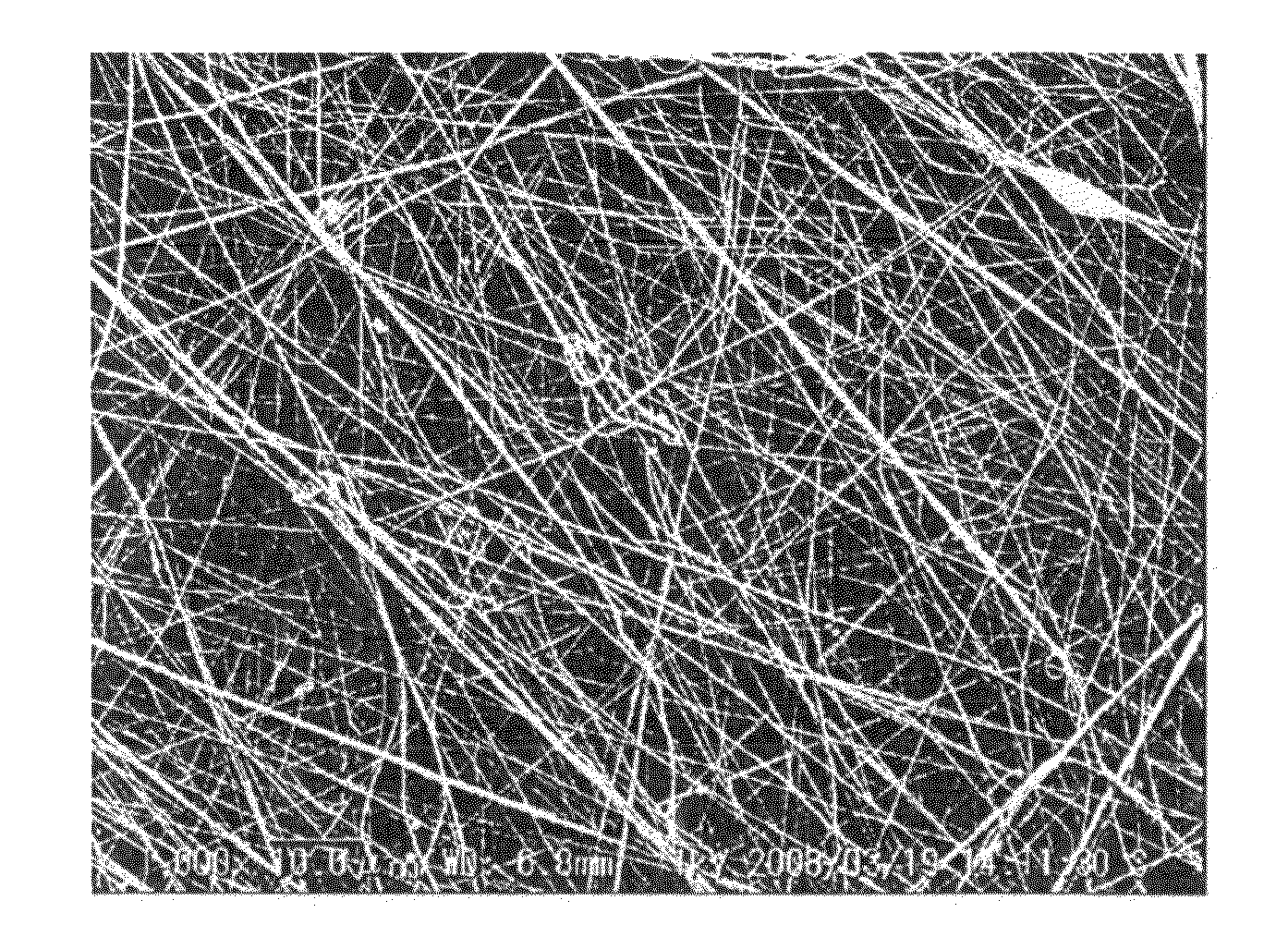
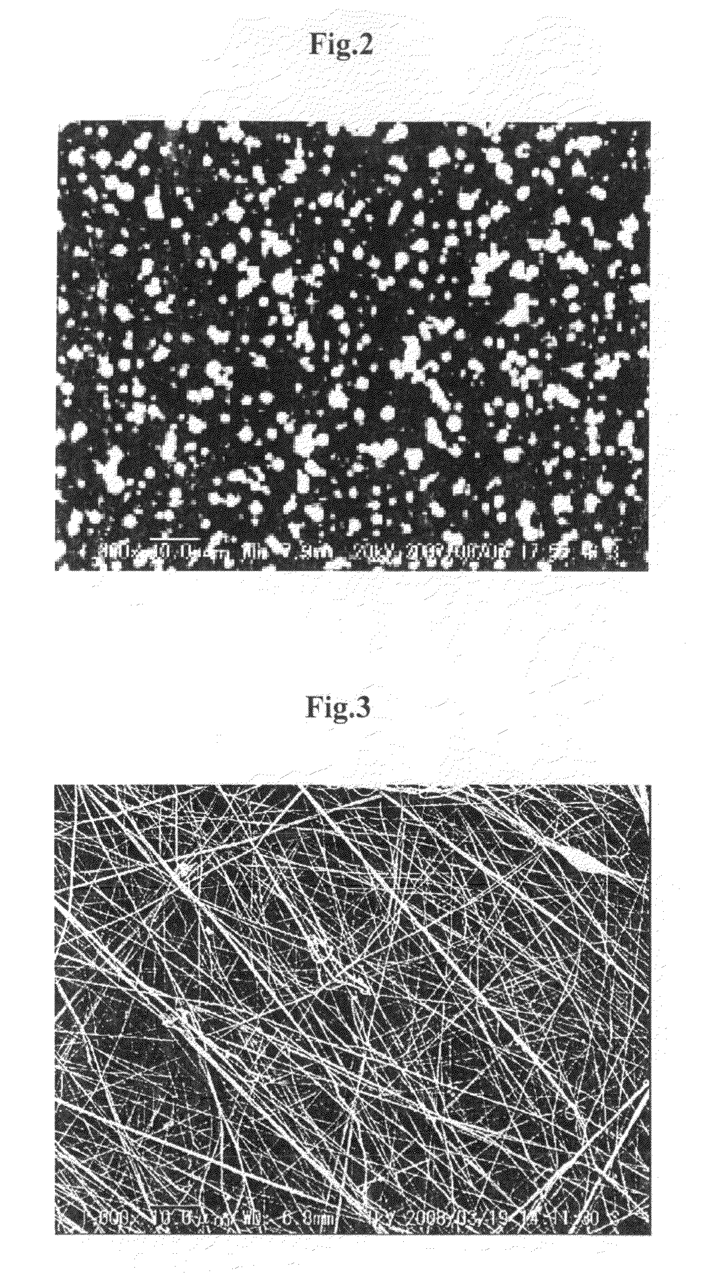
[0093]A solution containing PVDF of 10% by weight, Nafion of 8.3% by weight, water of 4.2% by weight, 1-propanol of 4.2% by weight, and DMAc of 73.3% by weight was prepared as a solution containing the non-electrolytic polymer and the electrolytic polymer. The resultant solution was attempted to be used for the electro spinning under conditions the same as those of the Comparative Example 1. The solution easily gelated and was therefore warmed to be maintained at a temperature of approximately 45° C. during the electro spinning. FIG. 3 is a photograph in which platinum is vapor-deposited on the resultant fibers, taken using SEM at a magnification of 1000×.

[0094]

[0095]As illustrated in FIG. 3, fibers each having a size of 200 nm were produced by the electro spinning, and hybrid polymer fiber material having a thickness of 50 μm and consisting of the fibers was produced. Furthermore, the hybrid polymer fiber materials were stacked in a planar manner, thereby producing a flat film of n...

example 2

[0096]A solution containing PVDF of 15% by weight, Nafion of 4.2% by weight, water of 2.1% by weight, 1-propanol of 2.1% by weight, and DMAc of 76.6% by weight was prepared as a solution containing the non-electrolytic polymer and the electrolytic polymer. The resultant solution was attempted to be used for the electro spinning under conditions the same as those of the Comparative Example 1. The solution was easily gelated and was therefore warmed to be maintained at a temperature of approximately 45° C. during the electro spinning. FIG. 4 is a photograph in which platinum is vapor-deposited on the resultant fibers, using SEM at a magnification of 1000×.

[0097]

[0098]As illustrated in FIG. 4, fibers each having a size of 400 nm were produced by the electro spinning, and hybrid polymer fiber material having a thickness of 50 μm and consisting of the fibers produced. Furthermore, the hybrid polymer fiber materials were stacked in a planar manner, thereby producing a flat film of nonwove...


PUM

PropertyMeasurementUnit
temperatureaaaaaaaaaa
diameteraaaaaaaaaa

Abstract

There is provided a hybrid polymer fiber material containing a non-electrolytic polymer and an electrolytic polymer and having properties and advantages of both polymers, and provided a method of producing the hybrid polymer fiber material, and provided a filter made of the hybrid polymer fiber material. A voltage is applied between a nozzle 1 and a target 3 (opposite surface) such that the nozzle 1 is positive and such that the target 3 is negative. Then, the mixed solution of the non-electrolytic polymer and the electrolytic polymer is ejected from the nozzle 1 to the target 3, so that hybrid polymer fiber material 2 containing the non-electrolytic polymer and the electrolytic polymer is accumulated on the target 3. The hybrid polymer fiber material 2 is used as a filter for fluid filtration.

Description

FIELD OF THE INVENTION[0001]The present invention relates to a hybrid polymer fiber material that contains a non-electrolytic polymer and an electrolytic polymer and relates to a method of producing the hybrid polymer fiber material. Furthermore, the present invention relates to a filter that is made of the hybrid polymer fiber material and that is used for fluid filtration.BACKGROUND OF THE INVENTION[0002]In order to highly purify ultrapure water used in a semiconductor manufacturing process or the like, a pleated ion exchange filter is widely used. The pleated ion exchange filter is produced by forming a flat film, such as nonwoven fabric or a porous film, into a pleated shape.[0003]In the pleated ion exchange filter, a flow is likely to concentrate on the edge of the pleat. Therefore, sufficient removal of ion can not be provided in the significantly low concentration region. In addition, the film is so thin that ion capacity of the film is very small resulting in such a filter h...

Claims


Application Information

Patent Timeline
Patent Type & Authority Applications(United States)
IPC IPC(8): B01D39/16D04H11/00B29C47/00D04H1/728D04H3/02
CPCB01D39/1623B01D2239/0631B01D2239/10B01J20/26B01J20/28023D04H3/02C02F1/42C02F2103/04D01D5/0038D01F6/48D04H1/728B01J47/123B01J47/127Y10T442/637
Inventor KAWAKATSU, TAKAHIROKOBAYASHI, HIDEKIOGAWA, YUICHI
Owner KURITA WATER INDUSTRIES LTD
Why Eureka
Try Eureka