

Method and apparatus for detecting marine deposits
a technology of marine deposits and methods, applied in the field of oceanographic electromagnetic and magnetotelluric surveys, can solve the problems of complex 3-d interpretation of csem data, less success of csem in shallow water, and interference of electromagnetic noise with signals, so as to achieve precise synchronous detection, improve instrumental sensitivity, and improve the effect of sensitivity
- Summary
- Abstract
- Description
- Claims
- Application Information
AI Technical Summary
Benefits of technology
Problems solved by technology
Method used
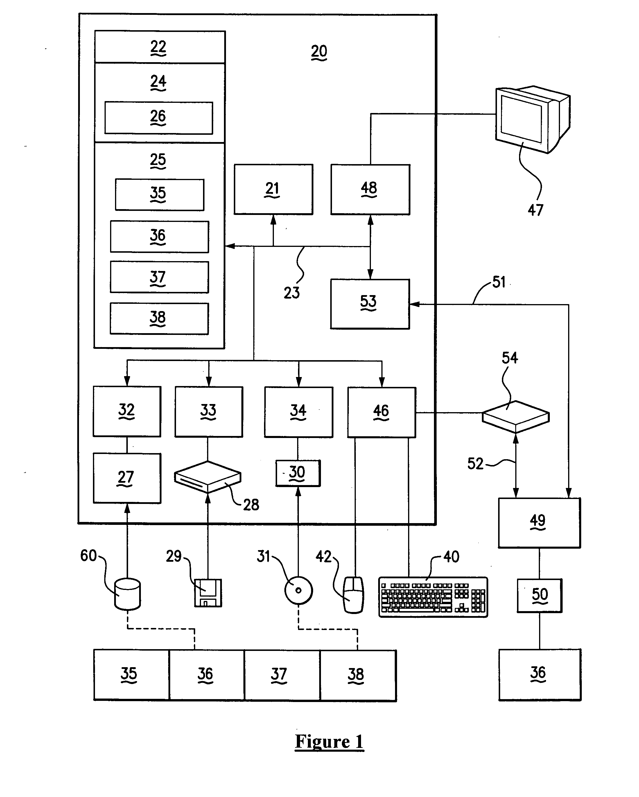
Image

Examples
Embodiment Construction
t using a logarithmic scale for wavelength to clarify the behaviour at shorter wavelengths;
[0037]FIG. 12 plots amplitudes of gradient tensor fluctuations 50 m above the ocean surface, for wavelengths up to 200 m
[0038]FIG. 13 is as for FIG. 12, but for wavelengths up to 5600 m;
[0039]FIG. 14 plots amplitude of magnetic gradient tensor fluctuations, for maximum wave height, as a function of wavelength for varying altitudes;
[0040]FIG. 15 is as for FIG. 14, but with a log scale for wavelength to clarify the behaviour at shorter wavelengths; and
[0041]FIGS. 16a to 16d are plots of velocity, electric current, magnetic field and magnetic field gradient, respectively, versus depth, for the case where v0=2 ms−1 and z0=1100 m, in a 4 km deep (σ=3.2 Sm−1) ocean with a 1 km thick conductive (σ′=1 Sm−1)seafloor.
DESCRIPTION OF THE PREFERRED EMBODIMENTS
[0042]Some portions of the detailed descriptions which follow are presented in terms of algorithms and symbolic representations of operations on data...
PUM
 Abstract
Description
Claims
Application Information