Semiconductor laser device and method of manufacturing the same
- Summary
- Abstract
- Description
- Claims
- Application Information
AI Technical Summary
Benefits of technology
Problems solved by technology
Method used
Image

Examples
first embodiment
Modification of First Embodiment
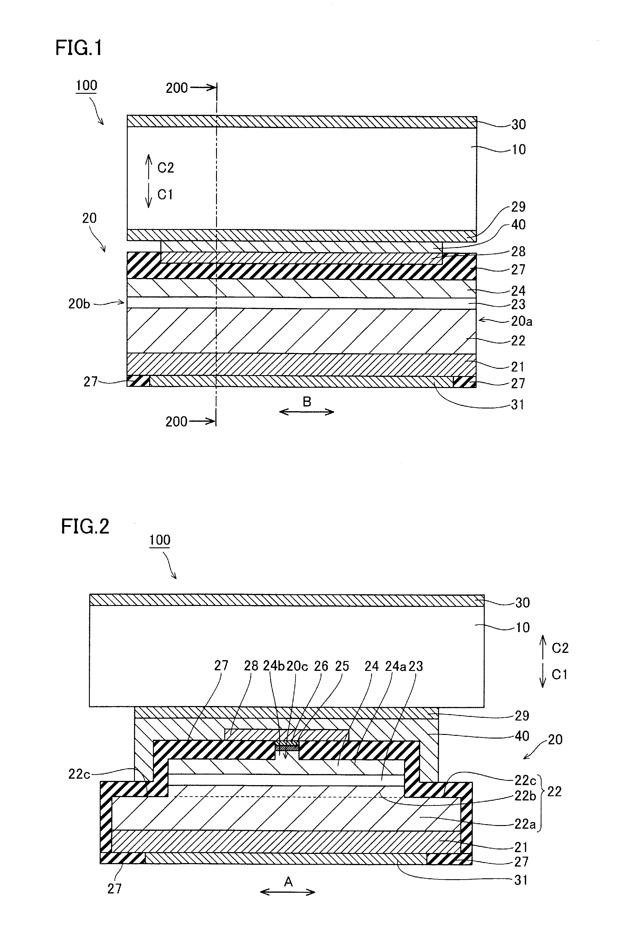
[0103]According to a modification of this first embodiment, a semiconductor laser device portion 20 is so formed that a width of a light-emitting surface 20a (light-reflecting surface 20b) in a direction A is uniformized in a thickness direction (direction C1) of semiconductor layers are uniformized, dissimilarly to the aforementioned first embodiment, and this will be now described with reference to FIGS. 2 and 14.
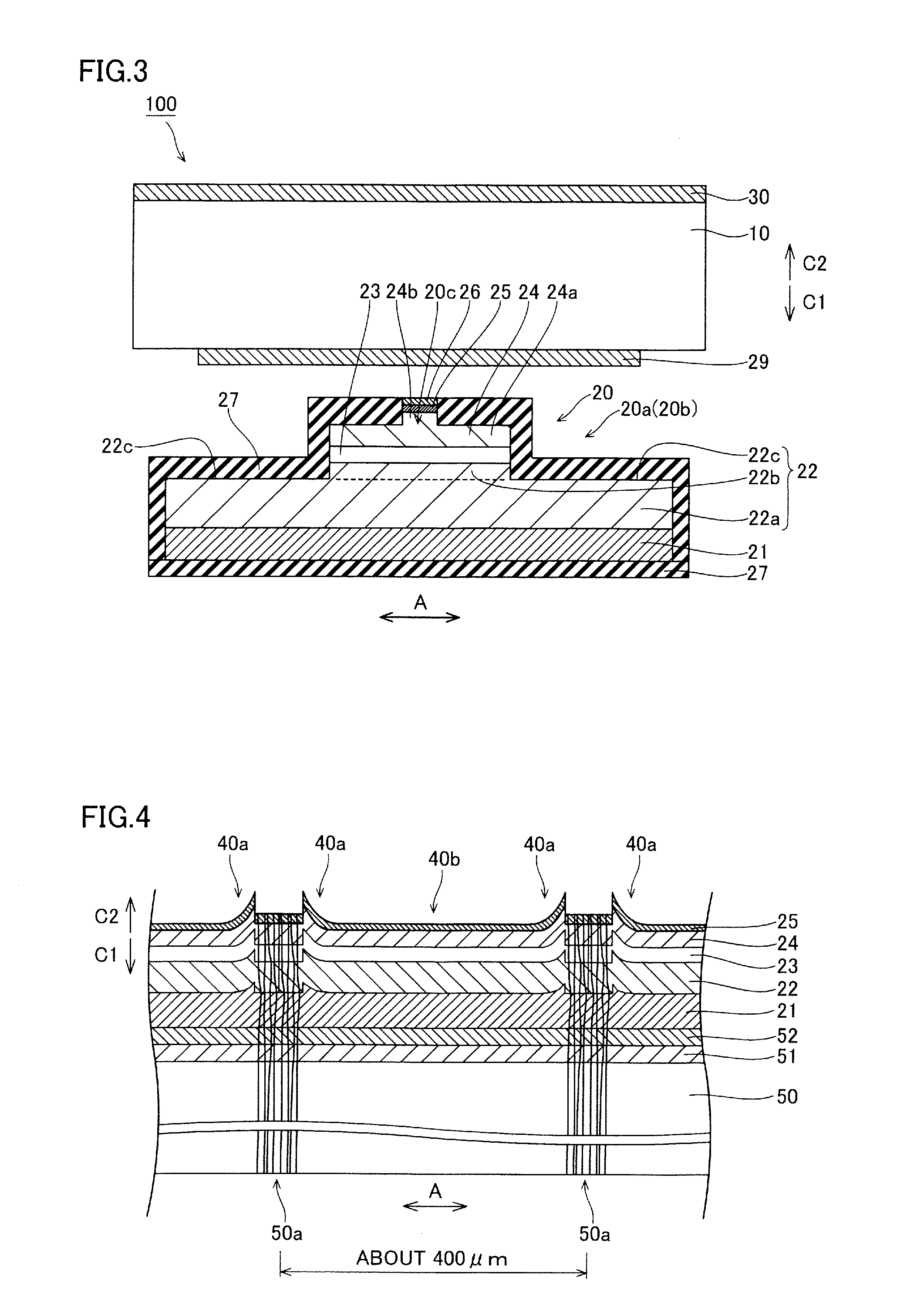
[0104]According to the modification of the first embodiment, as shown in FIG. 14, an n-type contact layer 21 and an n-type cladding layer 22 are formed to have widths of about 60 μm in the direction A on the light-emitting surface 20a (light-reflecting surface 20b) of the semiconductor laser device portion 20. An active layer 23 and a p-type cladding layer 24 are so formed on the n-type cladding layer 22 as to have substantially the same widths (about 60 μm) as the n-type cladding layer 22. Therefore, the semiconductor laser device portion ...
second embodiment
Modification of Second Embodiment
[0121]According to a modification of this second embodiment, semiconductor laser devices 155 each brought into a chip state and having only one ridge 20c (waveguide) is formed, dissimilarly to the aforementioned second embodiment, and this will be now described with reference to FIGS. 17, 19 and 20.
[0122]According to the modification of the second embodiment, in the semiconductor laser device 155, a semiconductor laser device portion 120a having the single ridge 20c is bonded onto a lower surface of a p-type Ge substrate 10, as shown in FIG. 20. In other words, in addition to division of the p-type Ge substrate 10 at device division positions P corresponding to both side ends of a semiconductor laser device portion 120, the p-type Ge substrate 10 and the semiconductor laser device portion 120 are divided at a device division position Q corresponding to a step portion 22c in a substantially central portion of the semiconductor laser device portion 120...
third embodiment
[0123]According to a third embodiment, a single semiconductor laser device portion 130 has substantially parallel three ridges 20c to each other, dissimilarly to the aforementioned second embodiment, and this will be now described with reference to FIGS. 18, 21 and 22. The semiconductor laser device portion 130 is an example of the “first semiconductor device portion” in the present invention.
[0124]According to the third embodiment, an n-type cladding layer 22 has a region 22a having a width of about 360 μm in a direction A and three regions 22b each having a width of about 60 μm in the direction A, as shown in FIG. 21. Thus, two recess portions 22d and step portions 22c are formed between the adjacent regions 22b and on both ends in the direction A respectively by an upper surface of the region 22a and side surfaces of the three regions 22b. An active layer 23 and a p-type cladding layer 24 are so formed on each of the three regions 22b as to have substantially the same widths (abo...
PUM
 Abstract
Description
Claims
Application Information
 - Generate Ideas
- Intellectual Property
- Life Sciences
- Materials
- Tech Scout
- Unparalleled Data Quality
- Higher Quality Content
- 60% Fewer Hallucinations
Browse by: Latest US Patents, China's latest patents, Technical Efficacy Thesaurus, Application Domain, Technology Topic, Popular Technical Reports.
© 2025 PatSnap. All rights reserved.Legal|Privacy policy|Modern Slavery Act Transparency Statement|Sitemap|About US| Contact US: help@patsnap.com