Production method of a coating layer for a piece of turbomachinery component, the component itself and the corresponding piece of machinery

a technology of turbomachinery and production method, which is applied in the direction of liquid fuel engines, vessel construction, marine propulsion, etc., can solve the problems of nickel coating dilatation, small cracks or fractures, and radial expansion of impellers, so as to reduce mechanical stress and vibration in the rotor, easy to coat a component, and reduce the mass of the component

Inactive Publication Date: 2011-01-20
NUOVO PIGNONE SPA
View PDF22 Cites 8 Cited by
  • Summary
  • Abstract
  • Description
  • Claims
  • Application Information

AI Technical Summary

Benefits of technology

[0047]Another advantage entailed is that it becomes possible to easily coat a component which has a very complex surface to be treated, such as, for example, the one of a tridimensional impeller of a centrifugal compressor or of an expander.
[0048]Another advantage is that producing the centrifugal impellers in a light alloy, significantly reduces the mass of the component, decreasing the mechanical stress and the vibrations in the rotor of the machine. Further advantages deriving from mass reduction are the increase of the number of turbomachinery stages and / or the increase of rotational speed.
[0049]Another advantage is that costs and production times are exceptionally lower, thus enhancing productivity.
[0050]Another advantage is that the high quality manufacture, due to the fact that nickel deposition is easily manageable, is extremely even and delivers a constant thickness.
[0051]Another advantage arises from the fact that the method is very versatile, because it can be implemented through automated processes in combination with possible partial manufacturing work, such as painting or others thereof
[0052]Another advantage is that it becomes easy to obtain a finished component having the theoretical fluid dynamics studied in the project, eventually keeping into account specific superficial increase coefficients.

Problems solved by technology

A major drawback linked to the use of nickel-plating to coat the centrifugal impellers of pieces of turbomachinery is that these impellers undergo radial expansions, due to the centrifugal force, when in use.
Therefore the nickel coating might dilate creating small cracks or fractures in which the corrosion process might start.
One of the main disadvantages in using these lighter alloys to fabricate centrifugal impellers is that they are subject to be eroded by the fluid which, flowing at high speeds, can cause the erosion, especially if the fluid contains liquid or solid particles.
The erosion, usually not significant in case of impellers made from the traditional heavy alloys, becomes very significant and potentially catastrophic for impellers in light alloy, due to the low hardness and resistance to erosion which characterise these materials.
The damage is also worsened by the rotational speed of the impellers, the higher the speed, the stronger the erosion: this problem limits the use of light alloys, such as aluminium, to build impellers having a high rotational speed.
A further difficulty is that the coatings for centrifugal impellers must also, in general, be “machineable” in the easiest and smoothest way to limit production costs.
Another downside is that the deposition of the coating layers must be carefully controlled to ensure project tolerances and at the same time to avoid unacceptable faults in the finished product, such as stains, coating delamination and failures, to remain within the border values typical for the specific coating.
Thus, at this moment, still withstanding the progresses made by technology, it is problematic and necessary to fabricate turbomachinery centrifugal impellers which will be lighter and more resistant to adapt to specific applications but which, at the same time, need to ensure at least the same resistance against solid particles and liquid drops erosion as the one ensured by “heavy” alloys.

Method used


Image

  • Production method of a coating layer for a piece of turbomachinery component, the component itself and the corresponding piece of machinery
  • Production method of a coating layer for a piece of turbomachinery component, the component itself and the corresponding piece of machinery
  • Production method of a coating layer for a piece of turbomachinery component, the component itself and the corresponding piece of machinery

Examples


Embodiment Construction

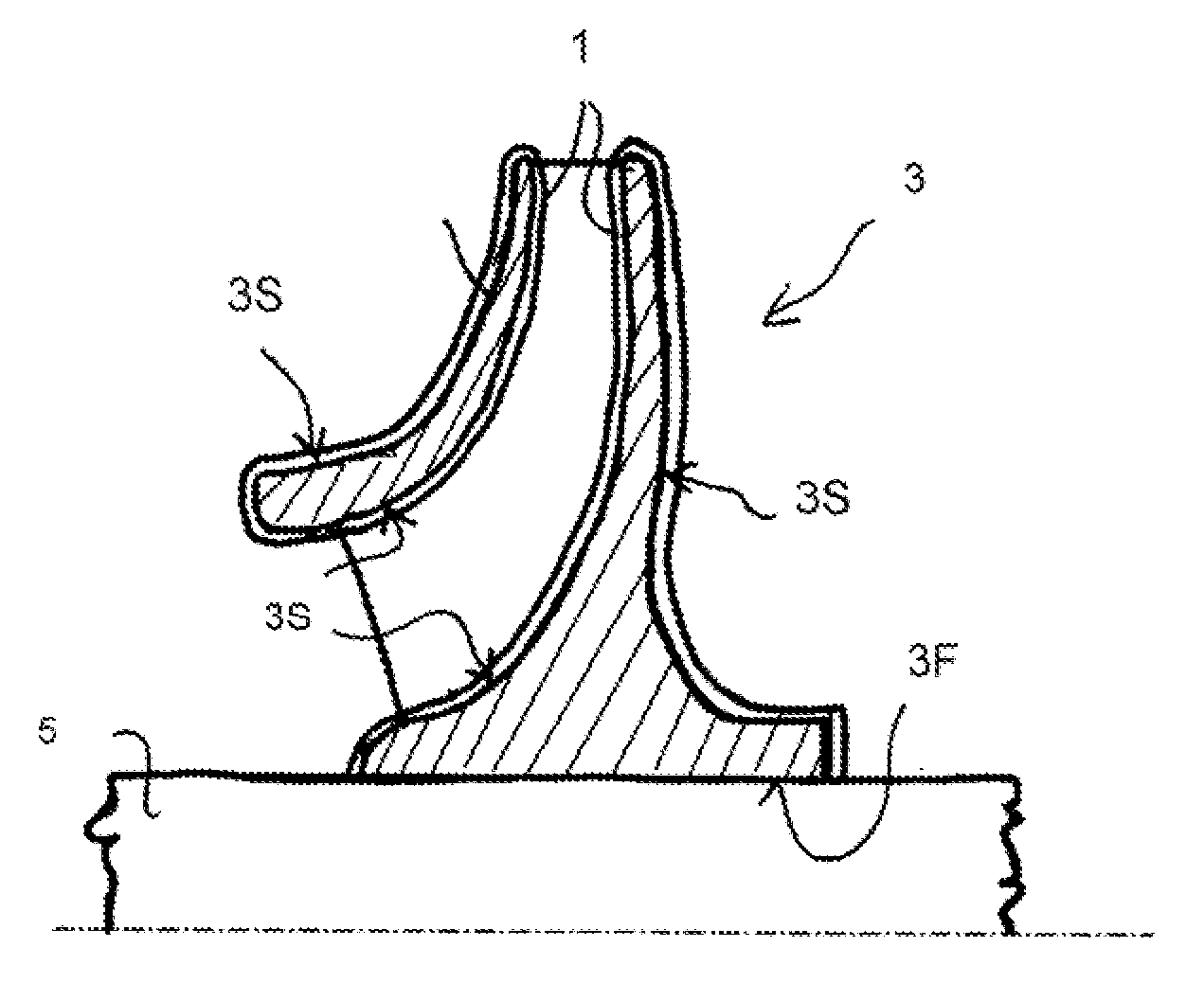
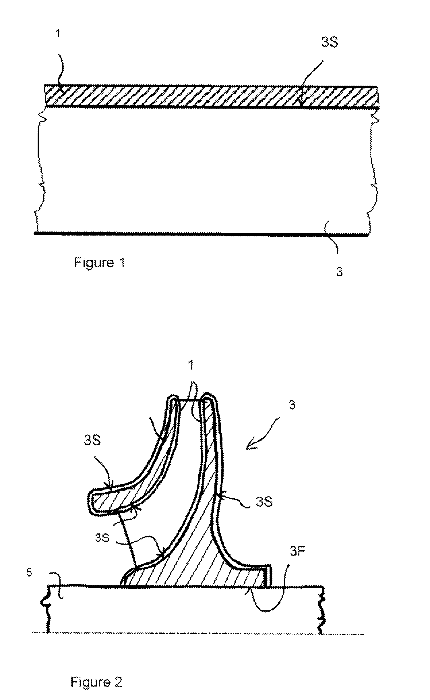
[0060]In the drawings, (to equal numbers correspond equal parts in all of them), a coating 1, as indicated in the invention, please see FIG. 1, is applied through chemical nickel plating on the surface to be treated 3S belonging to a centrifugal impeller 3 made out of light alloy.

[0061]The impeller can be of any kind, such as, for example centripetal, mixed flow or others.

[0062]FIG. 2 shows a partial section, not drawn to scale, of a centrifugal impeller 3 for a centrifugal compressor, coated with the above mentioned coating 1 as indicated in the invention and mounted on a shaft 5: please note that the surface 3S of the impeller 3 is both external and internal (internal channels), exception made for the hole 3F in which the shaft 5 is mounted.

[0063]In particular, the impeller 3 drawn in the picture is a three dimensional closed impeller; obviously the impeller could be of any other type, an open three dimensional impeller for example, or a closed two dimensional impeller or an open ...


PUM

PropertyMeasurementUnit
pHaaaaaaaaaa
mechanicalaaaaaaaaaa
chemicalaaaaaaaaaa

Abstract

A method to produce a turbomachinery impeller, which includes, at least, the following steps: creation of the impeller using a light alloy, and coating of the impeller with a nickel-plating coating.

Description

CROSS-REFERENCE TO RELATED APPLICATIONS[0001]This application claims priority under 35 U.S.C. §119(a)-(d) or (f) to prior-filed, co-pending Italian patent application serial number CO2009A000024, filed on Jul. 15, 2009, which is hereby incorporated by reference in its entirety.BACKGROUND OF THE INVENTION[0002]1. Field of Invention[0003]This invention relates to a production method regarding a coating layer for a turbomachinery component. It also relates to the component itself and the piece of machinery where the component is installed.[0004]2. Description of the Prior Art[0005]Turbomachinery impellers are crucial components because they interact with the process fluids and also because they endure continuous mechanical, chemical and thermal stress.[0006]These components are traditionally produced with “heavy” alloys so that a high degree of durability is ensured during operation.[0007]By “heavy” alloy is usually meant a metal based alloy: the metal has a high atomic number, such as...

Claims


Application Information

Patent Timeline
Patent Type & Authority Applications(United States)
IPC IPC(8): F01D5/14B05D1/18B21D53/78
CPCF04D29/023Y10T29/49336F04D29/284F05D2230/314F05D2300/12F05D2300/17
Inventor GIOVANNETTI, IACOPOPAOLETTI, RICCARDOGIANNOZZI, MASSIMOGIORNI, EUGENIOAVANZINI, ANDREA
Owner NUOVO PIGNONE SPA
Why Eureka
Try Eureka