
Proton exchange polymer membrane using surface treatment technique based on direct fluorination, membrane-electrode assembly, and fuel cell comprising the same

a surface treatment technique and technology of proton exchange, applied in the direction of cell components, final product manufacturing, sustainable manufacturing/processing, etc., can solve the problems of fuel cell performance rapidly deterioration, low electrochemical unit cell performance of polymer membrane, and reduced catalytic activity, so as to improve proton conductivity and reduce methanol permeability , the effect of high dimensional stability

Inactive Publication Date: 2011-01-20
IUCF HYU (IND UNIV COOP FOUND HANYANG UNIV)
View PDF6 Cites 15 Cited by
  • Summary
  • Abstract
  • Description
  • Claims
  • Application Information

AI Technical Summary

Benefits of technology

[0019]Therefore, the present invention has been made in view of the above problems, and it is an object of the present invention to provide a proton exchange polymer membrane with excellent electrochemical properties whose surface is treated by direct fluorination using a fluorine gas having high reactivity.
[0027]The proton exchange polymer membrane of the present invention exhibits improved proton conductivity, high dimensional stability, and decreased methanol permeability through introducing hydrophobic fluorine having high electronegativity to the surface of the polymer membrane. Therefore, the proton exchange polymer membrane with excellent electrochemical properties of the present invention can be preferably utilized as polymer electrolyte membrane for fuel cell, generating electric energy from chemical energy of fuels.

Problems solved by technology

Thus it has high interfacial resistance between the polymer electrolyte membrane and the catalyst layers and forms inappropriate triple phase boundary, thereby the polymer membrane has low electrochemical unit cell performance.
In addition, by repeating the humid / dry condition according to the operation of the fuel cell, delamination of the electrode layers from the electrolyte membrane in MEA is occurred, and as a result, the fuel cell performance is rapidly deteriorated.
However, despite the improvement in the adhesiveness between the electrolyte membrane and the catalyst layer, these attempts are still restricted in their use, because of the problems such as limits to dissolution of the polymer used as a catalyst binder, significantly reduced catalytic activity due to inappropriate solvent selection, low electrochemical unit cell performance in spite of high proton conductivity, and low chemical / electrochemical stability.
However, in this case, there is a problem that the condensation reaction is interfered with the high electronegativity of fluorine, and as a result, it has a limitation of obtaining hydrocarbon polymer having a high molecular weight.
In addition to the molecular weight reduction problem, there are problems of degradation of the polymer chains and difficulty in controlling a degree of sulfonation through a post-sulfonation process (Electrochimica Acta 49 (2004) 2315-2323).
However, the fluorination method according to above-mentioned patent has problems that additional costs for using a solvent, treatment after the use of the solvent and a catalyst are generated.
As a result, the fluorination has barely any influence on improvement in the proton conductivity of the polymer membrane.
Furthermore, there are problems that a great amount of time is required in drying after swelling and reacting the polymer in the solvent and the fluorination process becomes more complicated.

Method used


Image

  • Proton exchange polymer membrane using surface treatment technique based on direct fluorination, membrane-electrode assembly, and fuel cell comprising the same
  • Proton exchange polymer membrane using surface treatment technique based on direct fluorination, membrane-electrode assembly, and fuel cell comprising the same
  • Proton exchange polymer membrane using surface treatment technique based on direct fluorination, membrane-electrode assembly, and fuel cell comprising the same

Examples


example 1

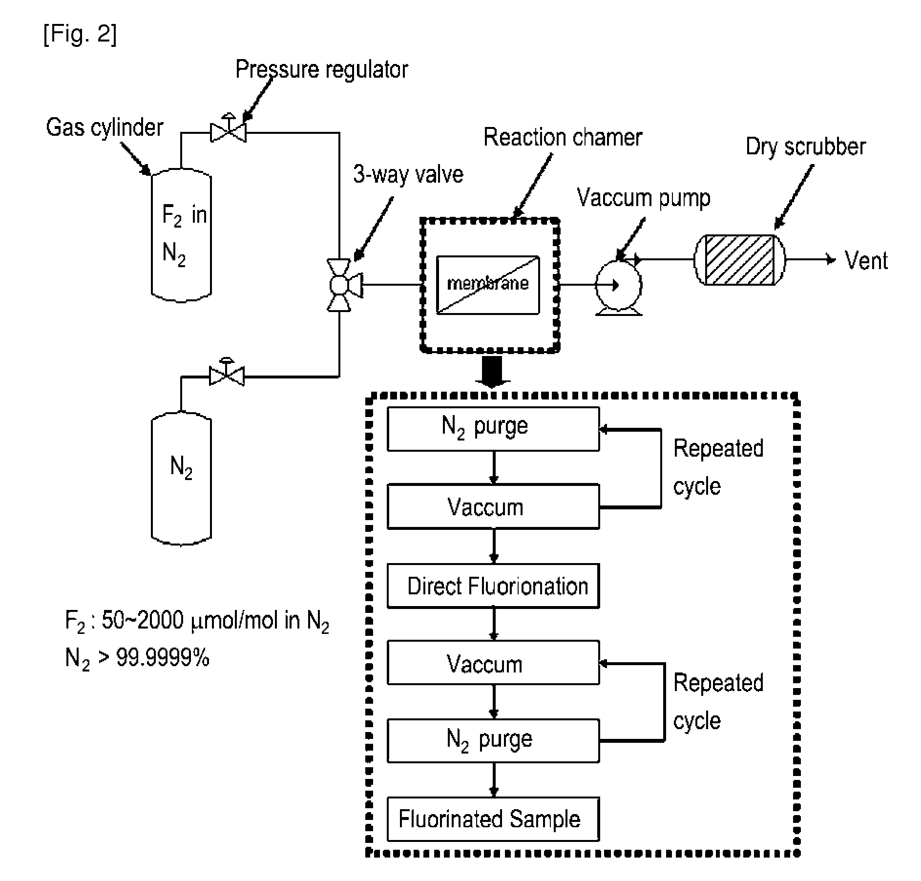
[0073]A surface of the sulfonated poly(arylene ether sulfone) membrane having a chemical structure in the following Formula 1 was fluorinated by dry direct fluorination process based on the order illustrated in FIG. 2 using a fluorination reactor shown in FIG. 2. Specifically, a dried polymer electrolyte membrane is inserted into a fluorination reaction chamber, and the membrane is fixed thereto. Nitrogen gas was purged into the chamber, and then vacuumed out. By repeating this process, chemical substances that may reside in the chamber were removed. Thereafter, since the membrane may be damaged when fluorine gas is directly purged into the chamber, an inert gas, i.e., nitrogen gas was purged and mixed with the fluorine gas via a 3-way valve to minimize the damage. Then, the flat sheet membrane sample was fluorinated in the reactor at ambient temperature and pressure (25° C. and 1 atm), while inflowing the F2 gas of 50 ppm, for 5 minutes. To terminate the direct fluorination reactio...

example 2

[0074]A surface-fluorinated sulfonated poly(arylene ether sulfone) membrane was prepared in the same manner as in Example 1, except that the fluorination time was 10 minutes.

example 3

[0075]A surface-fluorinated sulfonated poly(arylene ether sulfone) membrane was prepared in the same manner as in Example 1, except that the fluorination time was 30 minutes.


PUM

PropertyMeasurementUnit
temperatureaaaaaaaaaa
pressureaaaaaaaaaa
degree of surface-fluorinationaaaaaaaaaa

Abstract

A proton exchange polymer membrane whose surface is treated by direct fluorination using a fluorine gas, a membrane-electrode assembly, and a fuel cell comprising the same are provided. The proton exchange polymer membrane of the present invention exhibits improved proton conductivity, high dimensional stability, and decreased methanol permeability through introducing hydrophobic fluorine having high electronegativity to the surface of the polymer membrane. Therefore, the proton exchange polymer membrane with excellent electrochemical properties of the present invention can be preferably utilized as polymer electrolyte membrane for fuel cell, generating electric energy from chemical energy of fuels.

Description

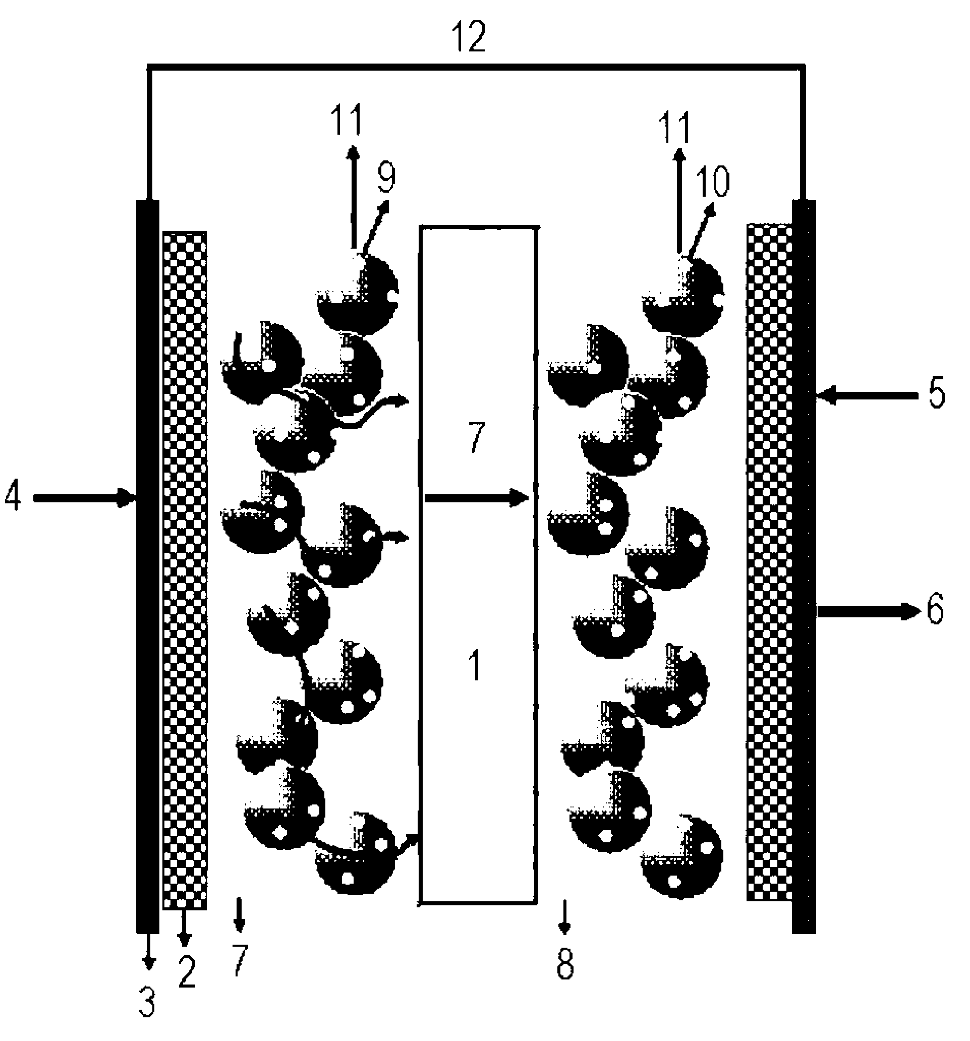
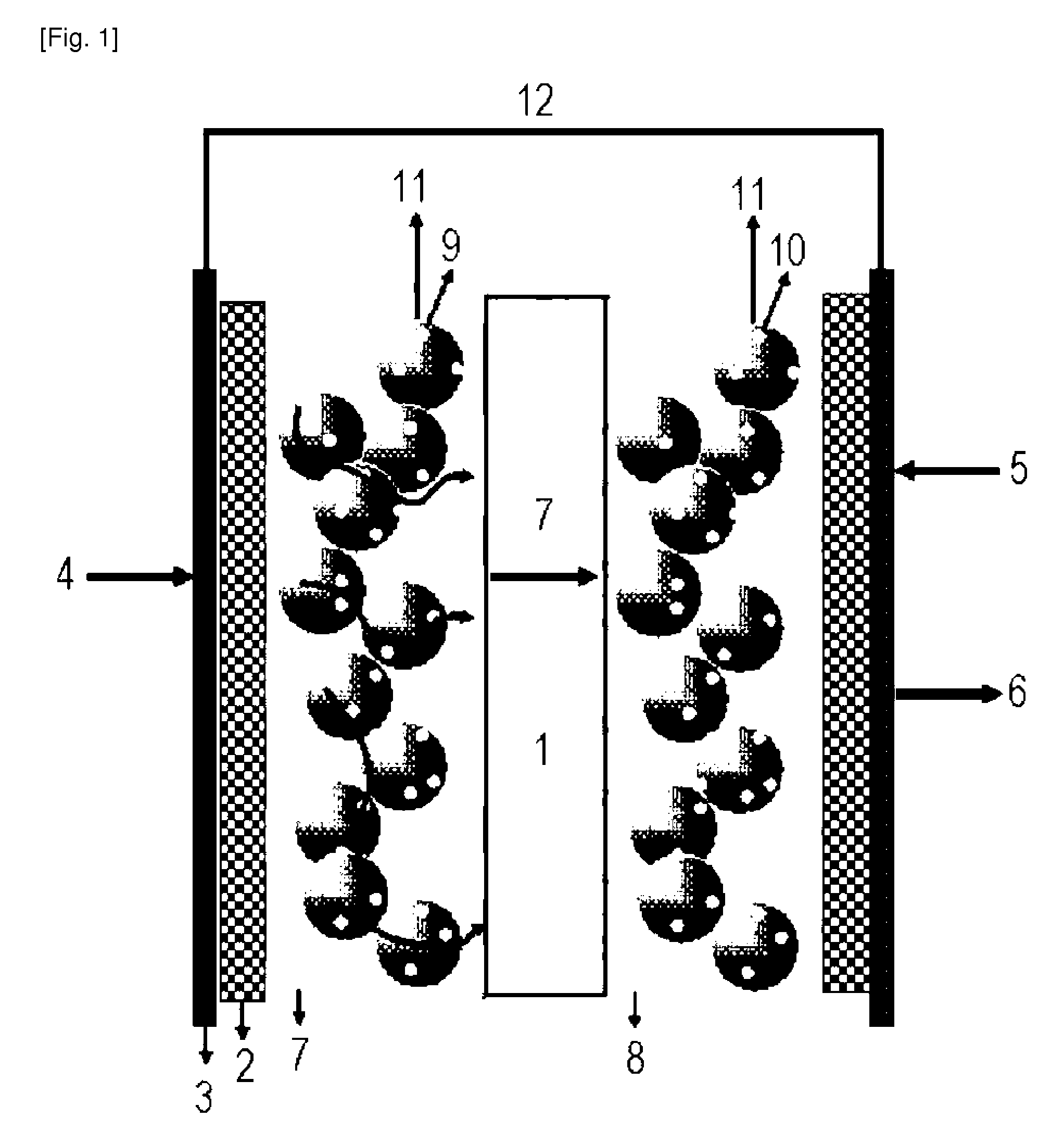
TECHNICAL FIELD[0001]The present invention relates to a proton exchange polymer membrane whose surface is treated based on direct fluorination using fluorine gas, a membrane-electrode assembly, and a fuel cell comprising the same.BACKGROUND ART[0002]A proton exchange polymer membrane fuel cell (PEMFC) and a direct methanol fuel cell (DMFC) based on a proton conductive polymer electrolyte membrane are energy generation systems having high energy efficiency and a low emission of air polluting substances. Particularly, unlike petroleum which is limited recoverable reserves, these fuel cells are advantageous in that the use of hydrogen or methanol as a fuel is almost perpetual. Thus, the fuel cells have been studied with great interest as an alternative energy source.[0003]FIG. 1 is a basic schematic view of a membrane-electrode assembly (MEA) constituting a fuel cell for producing electric energy and water / heat.[0004]With reference to FIG. 1, A proton conductive polymer electrolyte mem...

Claims


Application Information

Patent Timeline
Patent Type & Authority Applications(United States)
IPC IPC(8): H01M8/10
CPCH01M8/1025H01M8/1027H01M8/103H01M8/1032H01M8/1034Y02E60/521H01M8/1048H01M8/1051H01M8/1088H01M2008/1095H01M8/1039Y02E60/50Y02P70/50H01M4/86H01M8/10
Inventor LEE, YOUNG-MOOLEE, CHANG-HYUNLEE, SANG-YUN
Owner IUCF HYU (IND UNIV COOP FOUND HANYANG UNIV)
Learn More