A key issue in developing integrated circuits of increased packing density and enhanced performance is the scaling of transistor elements, such as MOS transistor elements, to increase the number of transistor elements in order to enhance performance of modern CPUs and the like with respect to
operating speed and functionality.
Although the reduction of the
gate length is necessary for obtaining smaller and faster transistor elements, it turns out, however, that a plurality of issues are additionally involved to maintain proper transistor performance for a reduced
gate length.
For example, so-called short channel effects may occur for highly scaled transistor elements, resulting in a reduced
controllability of the channel region, which may result in increased leakage currents and generally in degraded transistor performance.
One challenging task in this respect is, therefore, the provision of appropriately designed junction regions in the form of shallow junctions, at least at the area in the vicinity of the channel region, i.e., source and drain extension regions, which nevertheless exhibit a moderately
high conductivity so as to maintain the resistivity in conducting charge carriers from the channel to a respective contact area of the drain and source regions at a relatively low level, while also controlling the parasitic drain / source
capacitance and the
electric field of the
cut-off region.
The introduction of a high
dose of dopants into a crystalline substrate area, however, generates heavy damage in the
crystal structure, and, therefore, one or more anneal cycles are typically required for activating the dopants, i.e., for placing the dopants at
crystal sites, and to cure the
crystal damage.
However, the electrically effective
dopant concentration is limited by the ability of the anneal cycles to electrically activate the dopants.
Moreover, besides the
dopant activation and the curing of crystal damage, dopant
diffusion may also occur during the annealing, which may lead to a “blurring” of the dopant profile.
On the other hand, the dopant
diffusion may also result in a migration of dopants from the shallow extension regions into a portion of the spacer structure, such as a
silicon dioxide etch stop or liner material, thereby contributing to a loss of dopants, which may not be readily taken into consideration due to the above-specified limitations.
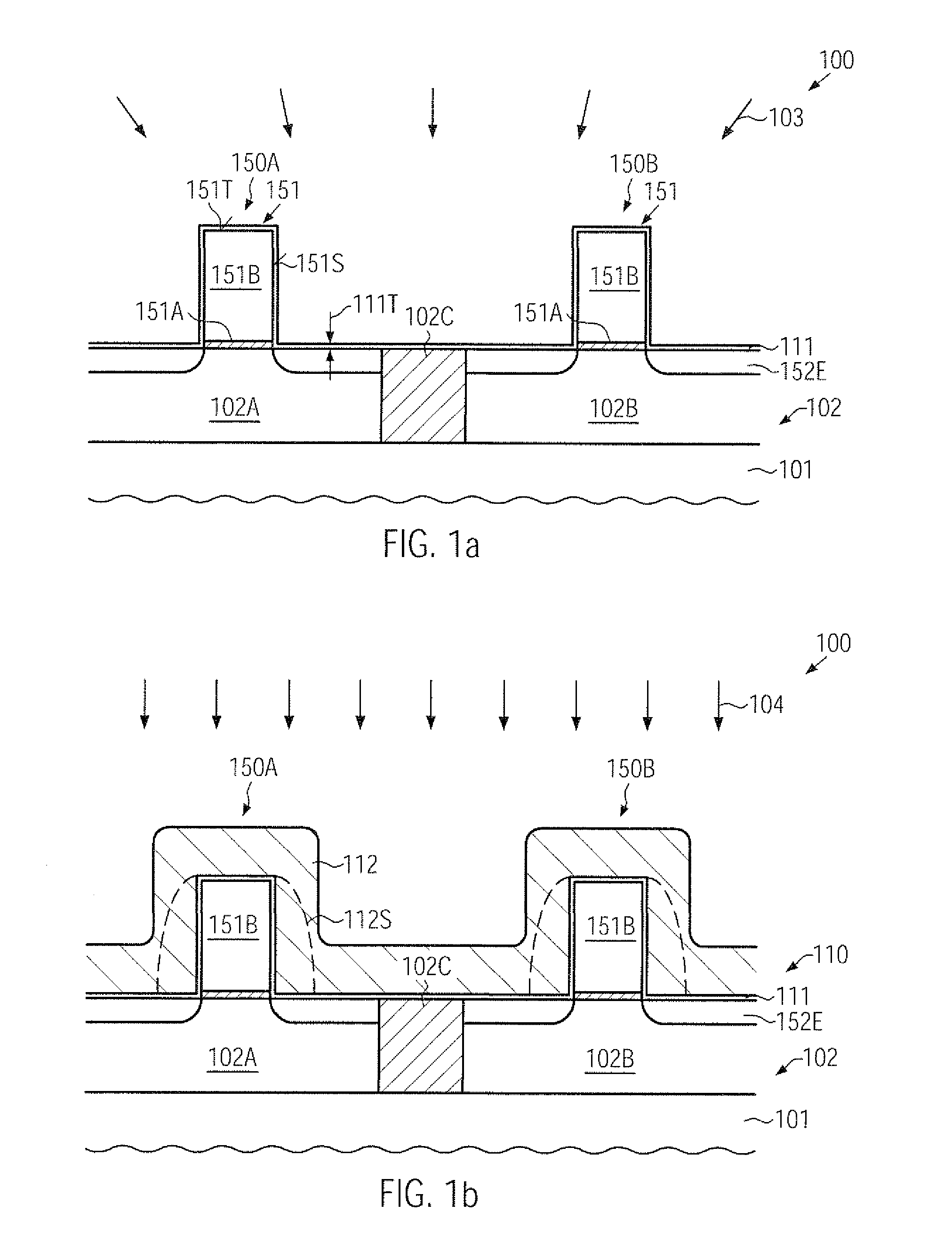
As is well known, one issue in shrinking overall dimensions of feature sizes is the requirement for patterning the features on the basis of advanced
lithography techniques in combination with complex etch processes.
Upon further shrinking transistor dimensions, the corresponding spacer structures also have to be adapted, wherein, however, the thickness of the etch stop material may not be correspondingly scaled down unless undue
material erosion of the etch stop material and of any underlying materials may be caused during the further
processing of the device.
Consequently, in such areas, the remaining etch stop material may have a significantly reduced thickness or may be entirely removed, thereby exposing these device areas, which may result in significant material loss in subsequent process steps.
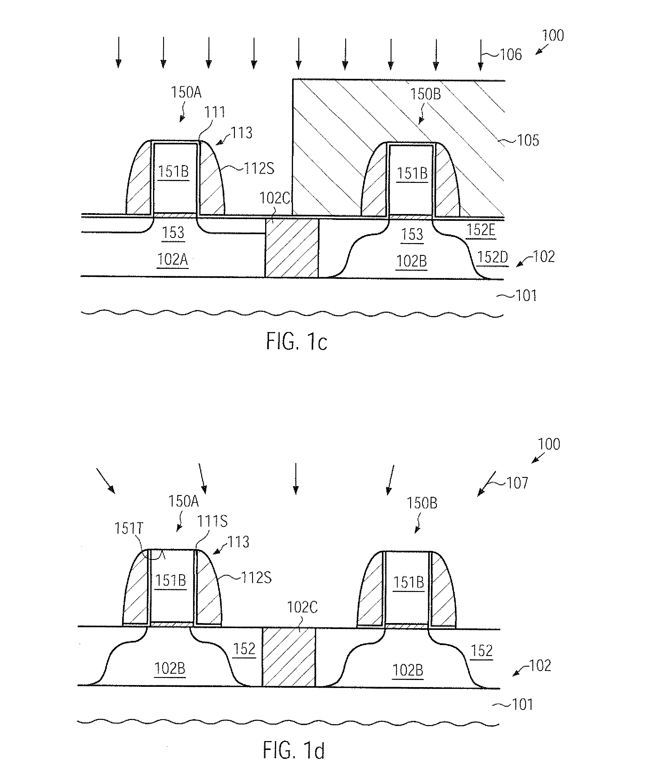
For instance, a significant material loss may occur in isolation structures relative to adjacent active
semiconductor regions, thereby contributing a pronounced surface
topography, which, in turn, may negatively affect the further
processing and thus the finally achieved performance of sophisticated transistor elements.
Due to the restrictions in view of a minimum thickness of the
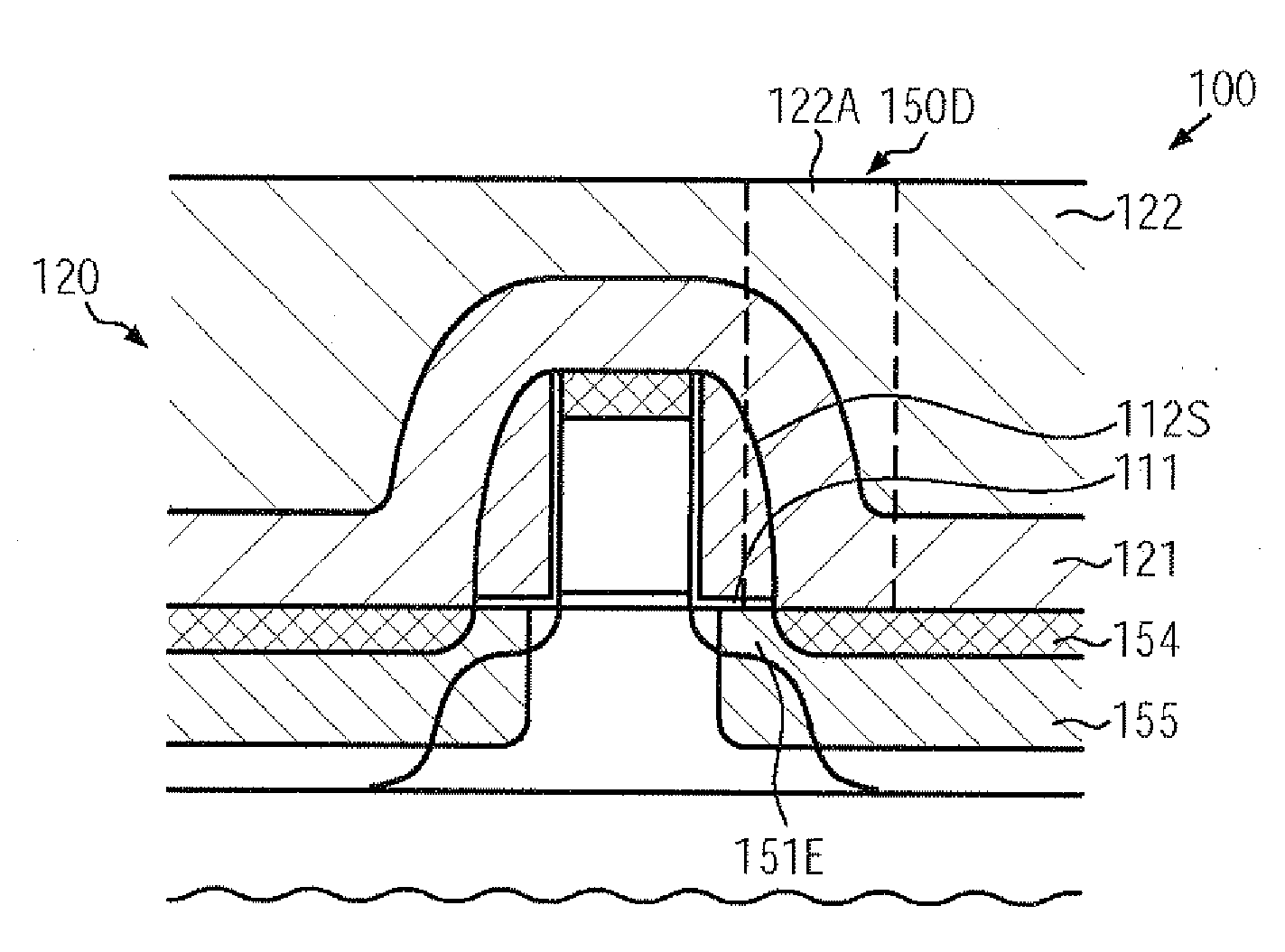
silicon dioxide etch stop material, however, a moderately thick liner may be in direct contact with the drain and source extension regions, which may result in a significant degree of dopant
diffusion during any high temperature processes, thereby resulting in a certain degree of “dopant depletion” of the drain and source extension areas.
Since a further increase in etch selectivity, which would allow the selection of a reduced thickness of the
silicon dioxide etch stop material, may be difficult to be achieved on the basis of well-established process recipes, a further device scaling may result in increased transistor variability due to a pronounced dopant out-diffusion from the drain and source extension areas.
Moreover, the implementation of other performance increasing mechanisms, such as the provision of strain-inducing
dielectric materials above basic transistor configurations and / or the provision of an embedded strain-inducing
semiconductor alloy in the drain and source areas of transistors, may also be affected by the fact that a significant
topography may be generated during the further
processing of the sophisticated transistor devices after forming the well-established
silicon dioxide /
silicon nitride-based spacer structures.

