Electron capture dissociation apparatus and related methods

a technology of electron capture and dissociation apparatus, which is applied in the direction of isotope separation, electric discharge tubes, particle separator tubes, etc., can solve the problems of high cost and technical complexity, inability to widely use penning trap-based instruments such as ftms, and inability to dissociate ions of large molecules. , to achieve the effect of low energy

Active Publication Date: 2011-03-03
AGILENT TECH INC
View PDF18 Cites 25 Cited by
  • Summary
  • Abstract
  • Description
  • Claims
  • Application Information

AI Technical Summary

Benefits of technology

[0008]Delivering electrons into an RF trapping region is further complicated by the effect that the RF fields have on the motion and energy of electrons. The RF voltage signal typically applied to the ion trap electrodes to confine the ions has a basic sine wave shape. Thus, over most of the RF cycle the magnitude of the voltage is a relatively large positive or negative value such that the ion trap electrodes will deflect electrons away from their intended path by attraction or repulsion. The sinusoidal waveform provides only a very short window of time, where the signal crosses zero volts, in which an electron beam may be successfully directed into the trap without being perturbed by the RF trapping field. Thus, for many applications it would be better to utilize rectangular impulses or other periodic waveforms that provide longer periods of zero RF voltage during which electrons may enter the trapping region, yet are still effective for trapping ions. Impulse-driven RF trapping for electron capture has been studied extensively by Zerega et al., International Journal of Mass Spectrometry, 132 (1994) 57-65, 67-72, and 135 (1994) 155-164; and by Sadat et al., International Journal of Mass Spectrometry, 107 (1991) 191-203. The latter has proposed the use of a particular form of impulse of the type V(t)=cost(Ωt) / (1-kcost(2Ω), where k=0.5-0.99. A wave form of this type was shown to have a stability region very similar to that of a quadrupole trapping field, but with the advantage that about 50% of time the RF voltage is near zero, thus making it ideal for low energy electron attachment studies.

Problems solved by technology

CID and IRMPD are not considered to be optimal techniques for dissociating ions of large molecules such as high molecular-weight or long-chain biopolymers (e.g., peptides, proteins, etc.).
For many types of large molecules these VE-based techniques are not able to cause the types of bond cleavages, or a sufficient number of these cleavages, so as to yield a complete structural analysis.
Penning trap-based instruments such as FTMS, however, are not in widespread use because of their high cost and technical complexity.
On the other hand, the implementation of ECD in Paul traps and multipole RF storage cells is challenging.
At these higher energies, parasitic ion formation by electron impact (EI) results in unwanted ions that contribute to the background signal and additional undesired ion-molecule reactions.
However, the simple lens system typically employed in such electron sources does not meet the requirements of ECD.
However, the large extraction voltage produces high energy electrons that are not suitable for ECD.
An additional problem associated with the formation of intense beams of electrons is the undesired beam divergence that occurs when electrons are decelerated.
If too much spatial spreading of the electron beam is permitted at the location of the target ions, there is no assurance that the electrons will have a low enough energy for ECD and the density (or intensity) of the electron beam at this point may be unacceptably low for producing an abundance of fragment ions.
Therefore, a conventional lens system is not effective for appropriately shaping the electron beam so that low-energy electrons can be delivered into the trapping region with the desired properties.
Delivering electrons into an RF trapping region is further complicated by the effect that the RF fields have on the motion and energy of electrons.
However, conventional techniques for increasing ion kinetic energy are difficult to implement in conjunction with ECD.

Method used


Image

  • Electron capture dissociation apparatus and related methods
  • Electron capture dissociation apparatus and related methods
  • Electron capture dissociation apparatus and related methods

Examples


Embodiment Construction

[0030]The subject matter disclosed herein generally relates to fragmenting ions by electron capture dissociation (ECD) and hot electron capture dissociation (HECD), and associated ion processing. Examples of implementations of methods and related devices, apparatus, and / or systems are described in more detail below with reference to FIGS. 1-11. These examples are described at least in part in the context of mass spectrometry (MS). However, any process that involves ion fragmentation may fall within the scope of this disclosure.

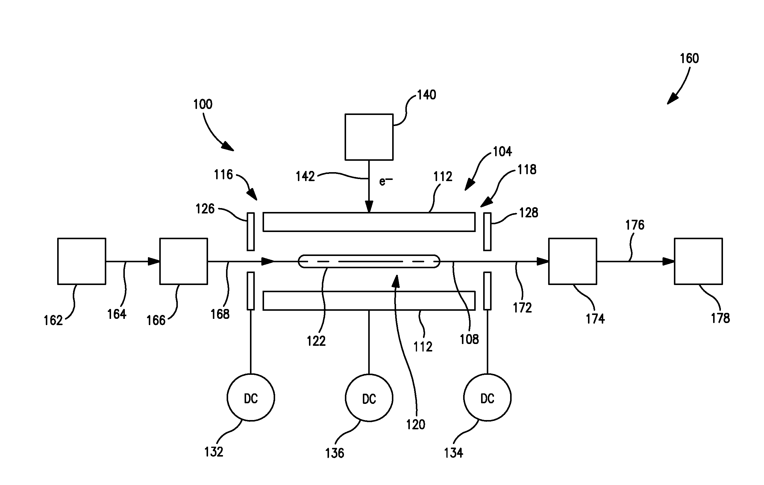
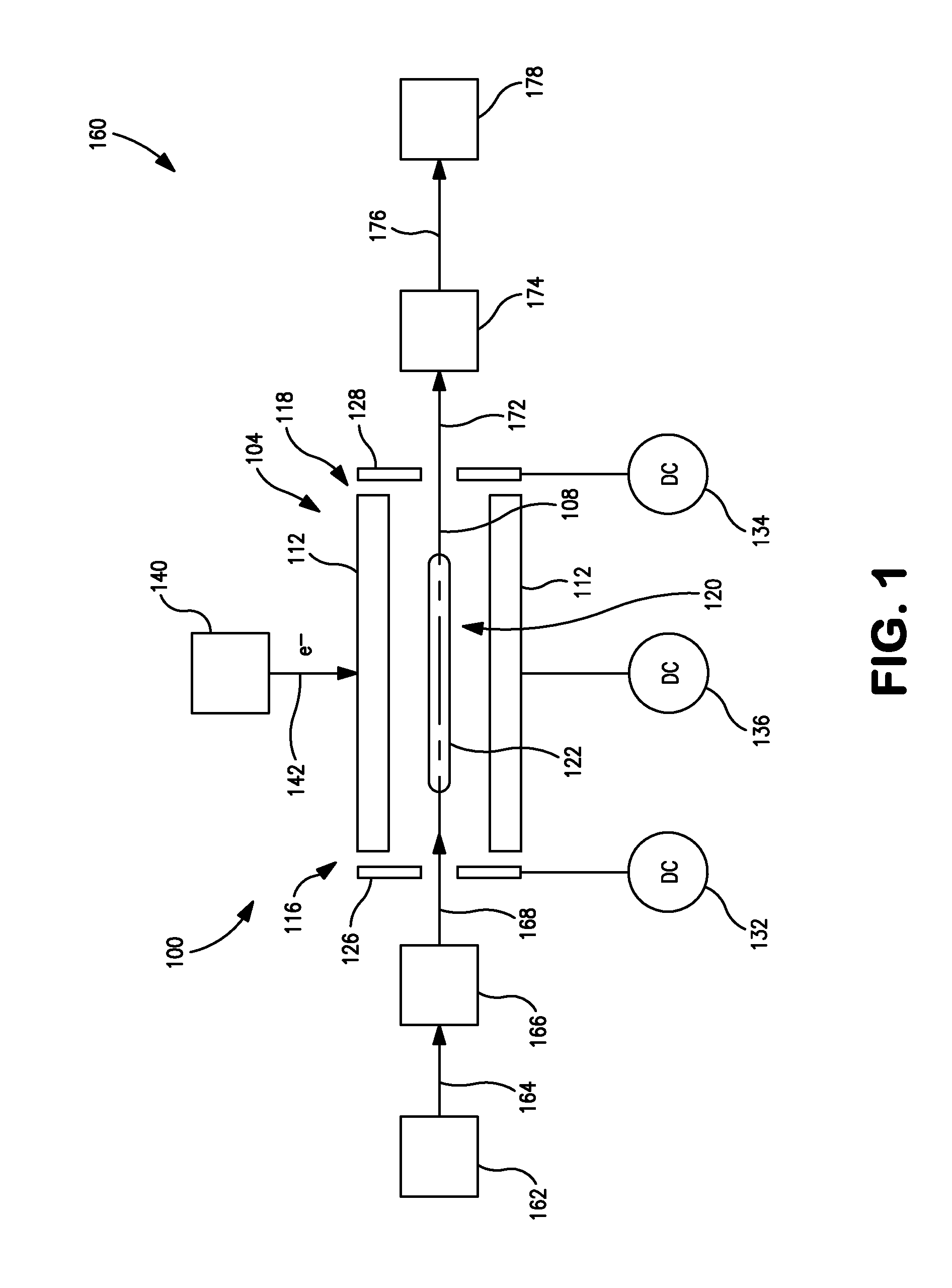
[0031]FIG. 1 is a schematic view of an example of an electron capture dissociation (ECD) apparatus 100 according to certain implementations of the present disclosure. The ECD apparatus 100 includes a linear (2D) multipole ion guide 104 arranged about a central axis 108. The ion guide 104 includes a plurality of ion guide electrodes 112 extending between a first axial end 116 and an opposing second axial end 118. For clarity, only two ion guide electrodes 112 a...


PUM


Abstract

An electron capture dissociation apparatus comprises ion guide electrodes, an electron emitter, and an electron control device. The ion guide electrodes are arranged along a central axis and spaced circumferentially to circumscribe an interior space extending along the central axis. The electron emitter is disposed outside the interior space. The electron control device is configured for focusing an electron beam from the electron emitter toward the central axis, along a radial electron beam direction between two of the ion guide electrodes, and for decelerating the electron beam in a DC decelerating field of adjustable voltage potential directed along the electron beam direction.

Description

FIELD OF THE INVENTION[0001]The present invention relates generally to fragmenting ions by electron capture dissociation, particularly in an ion trap driven by electric fields without magnetic fields.BACKGROUND OF THE INVENTION[0002]An ion trap is commonly utilized in a mass spectrometer (MS) as a means for controlling and spatially confining the motions of ions for various purposes. The theory, design and operation of various types of ion traps and associated mass spectrometers are well-known to persons skilled in the art and thus need not be detailed in the present disclosure. One common class of ion traps is the Penning trap, or ion cyclotron resonance (ICR) cell, marketed commercially as a Fourier Transform Mass Spectrometer (FTMS). The Penning trap uses an arrangement of electrodes to apply fixed magnetic and electric fields to confine ions in the radial and axial directions, respectively. An alternating electric field is used to resonantly excite the ions for determination of ...

Claims


Application Information

Patent Timeline
Patent Type & Authority Applications(United States)
IPC IPC(8): H01J49/26
CPCH01J49/0054
Inventor WELLS, GREGORY J.
Owner AGILENT TECH INC
Why Eureka
Try Eureka