Airfoil and process for depositing an erosion-resistant coating on the airfoil

a technology of airfoil and airfoil layer, which is applied in the direction of chemical vapor deposition coating, climate sustainability, machines/engines, etc., can solve the problems of reducing the fuel efficiency of the engine, reducing the efficiency of the compressor, and prone to ingesting significant amounts of particulates

Inactive Publication Date: 2011-03-03
GENERAL ELECTRIC CO
View PDF17 Cites 35 Cited by
  • Summary
  • Abstract
  • Description
  • Claims
  • Application Information

AI Technical Summary

Benefits of technology

[0012]A particular advantage of the process is the ability to selectively deposit a relative thin coating on the concave (pressure) airfoil surface of a blade that is prone to erosion, while avoiding the convex (suction) surface of the blade at which particle impacts can lead to unfavorable aerodynamic surface conditions if the convex surface was protected by a hard erosion-resistant coating. The invention has the further advantage of being capable of depositing thinner PVD coatings as compared to coatings deposited by thermal spray processes such as HVOF. As a result, the coatings are well suited for use as protective coatings on compressor blades of gas turbine engines without contributing excessive weight or adversely affecting desirable properties of the blades.

Problems solved by technology

Gas turbine engines are particularly prone to ingesting significant amounts of particulates when operated under certain conditions, such as in desert environments where sand ingestion is likely.
Because the airfoil 12 is typically formed of a metal alloy that is at least somewhat ductile, particle impacts can deform the leading edge 14, forming burrs that can disturb and constrain airflow, degrade compressor efficiency, and reduce the fuel efficiency of the engine.
The result is that the airfoil 12 gradually thins and loses its effective surface area due to chord length loss, resulting in a decrease in compressor performance of the engine.
Due to their location near the entrance of the engine, compressor blades suffer from both impact and erosion damage along their flowpath surfaces, particularly impact damage along their leading edges and erosion damage on their pressure (concave) surfaces.
Hard coatings such as TiN have been used to alleviate damage to the surfaces of compressor blade airfoils, but the ceramic nature of these coatings makes them less capable of resisting impact damage by especially large particles impacting the coating on trajectories that are nearly perpendicular to their surfaces.
However, particles impacting at high impact angles and high impact velocities can cause the coating on the nose of the airfoil to be eroded away, after which the remaining coating on either side of the airfoil, both concave and convex, tends to retard the erosion of the adjacent metal.
This problem can be very severe with thick HVOF coatings, leading to what has been termed bird beak, fish mouth, or bird mouth, and result in very unfavorable aerodynamic conditions that reduce the efficiency of the compressor.
Finally, the required thickness of HVOF coatings can result in excessive weight that may negatively affect blade fatigue life (for example, high-cycle fatigue (HCF)).
However, the sensitivity of PVD coatings to the high impact erosion of large particles, impacting at high velocity and high impact angle, have been found to cause the degradation rate of these coatings to vary significantly in adjacent locations on the same airfoil.
A problem shared by both HVOF and PVD erosion-resistant coatings is the deterioration of the airfoil surface roughness due to erosion and particle ingestion, which if sufficiently severe can reduce the efficiency of the compressor.

Method used


Image

  • Airfoil and process for depositing an erosion-resistant coating on the airfoil
  • Airfoil and process for depositing an erosion-resistant coating on the airfoil
  • Airfoil and process for depositing an erosion-resistant coating on the airfoil

Examples


Embodiment Construction

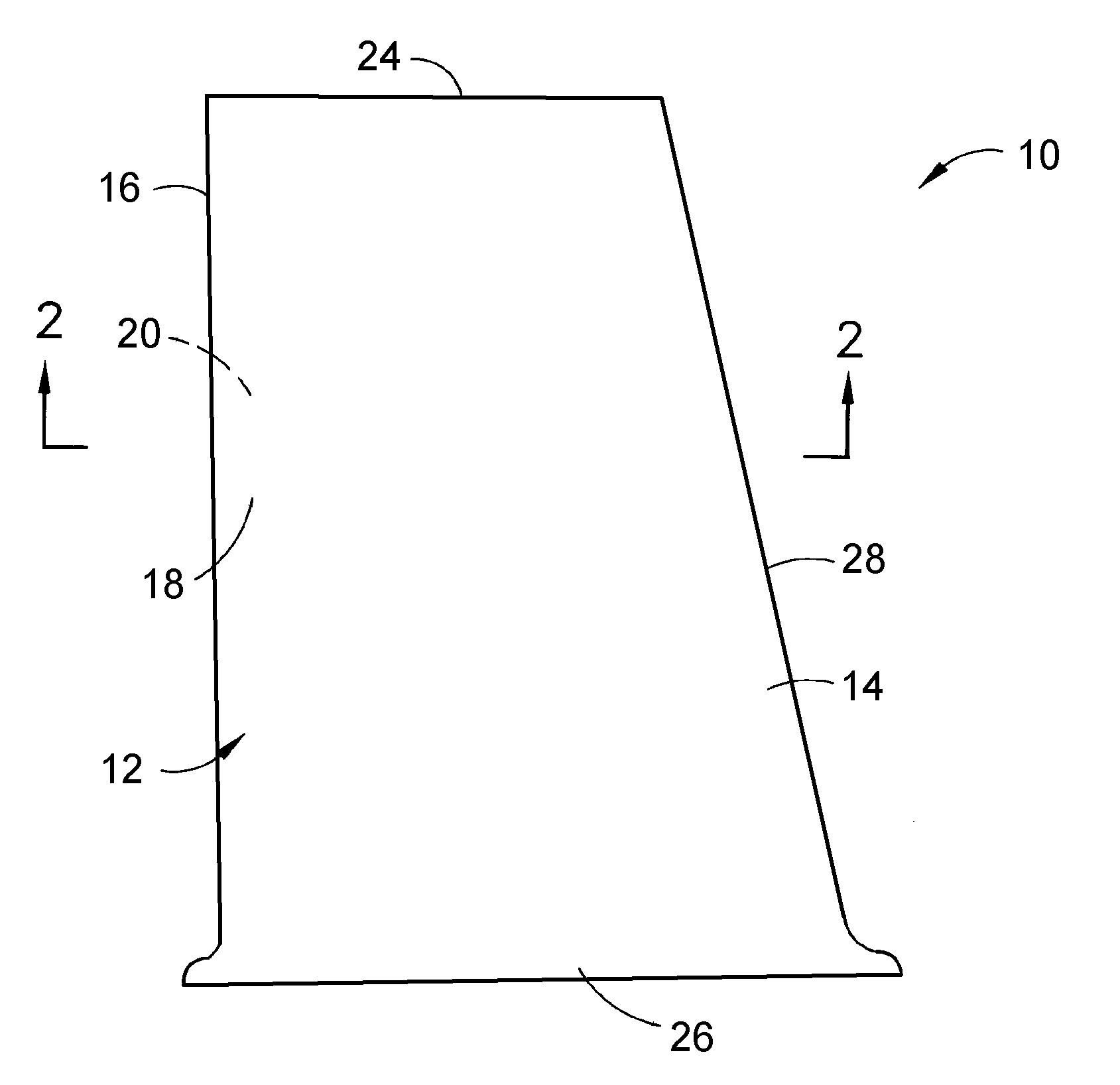
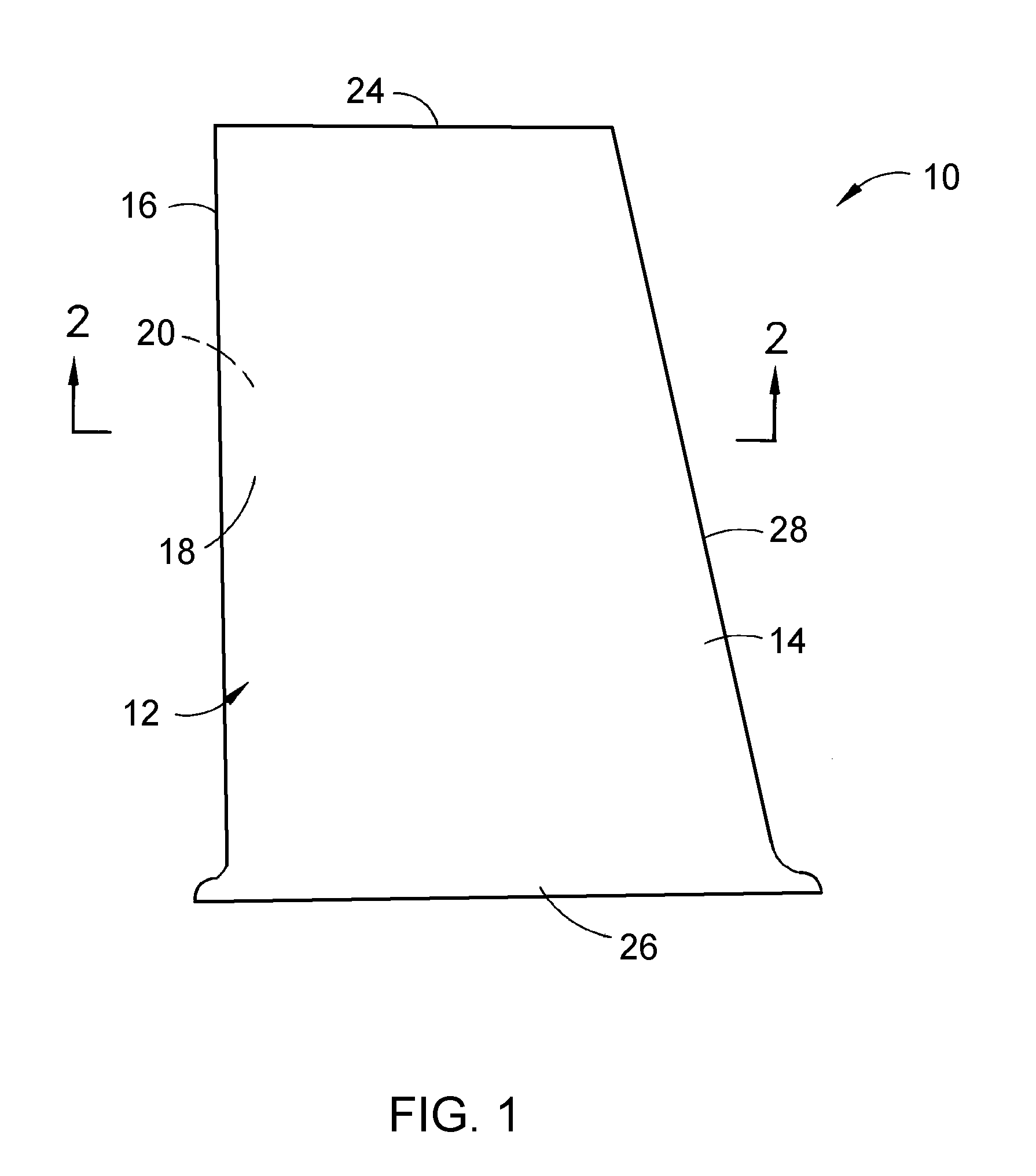
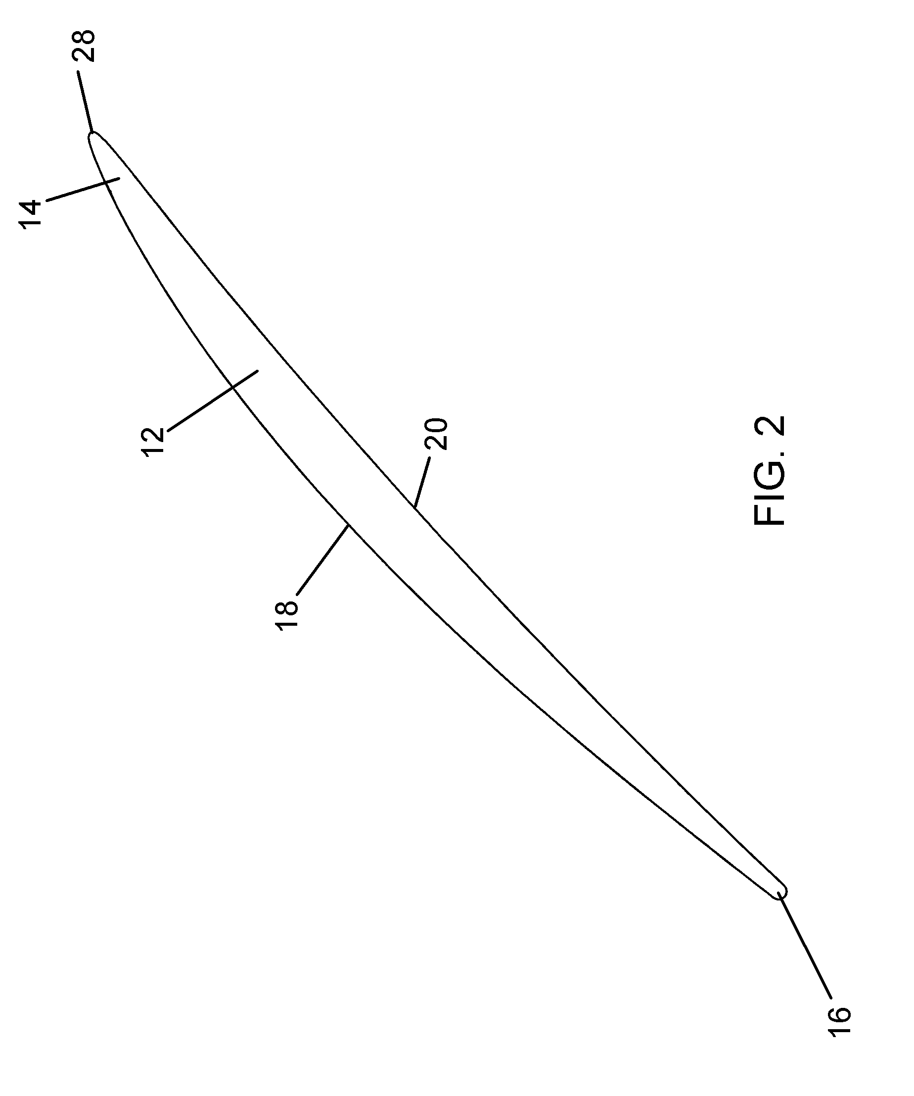
[0029]As previously described, FIGS. 1 and 2 represent the airfoil 12 of a gas turbine engine compressor blade 10. The present invention is particularly well suited for compressor blades of aircraft gas turbine engines, but is applicable to airfoil components used in other applications.

[0030]The blade 10 is formed of a material that can be formed to the desired shape and withstand the necessary operating loads at the intended operating temperatures of the gas turbine compressor in which the blades will be installed. Examples of such materials include metal alloys that include, but are not limited to, titanium-, aluminum-, cobalt-, nickel-, and steel-based alloys. When the blade 10 is installed in the compressor section of a gas turbine engine, the convex (suction) and concave (pressure) surfaces 18 and 20 of the blade 10 define what will be termed herein flowpath surfaces, in that they are directly exposed to the air drawn through the engine. The flowpath surfaces of the blade 10 ar...


PUM

PropertyMeasurementUnit
thicknessaaaaaaaaaa
thicknessaaaaaaaaaa
thicknessaaaaaaaaaa

Abstract

A process for depositing coatings, and particularly erosion-resistant coatings suitable for protecting surfaces subjected to collisions with particles, such as a compressor blade of a gas turbine engine. The blade has an airfoil comprising oppositely-disposed convex and concave surfaces, oppositely-disposed leading and trailing edges defining therebetween a chord length of the airfoil, and a blade tip. An erosion-resistant coating is present on at least the concave surface, but not on the convex surface within at least 20% of the chord length from the leading edge.

Description

BACKGROUND OF THE INVENTION[0001]The present invention generally relates to coatings and coating processes, and more particularly to a process for depositing erosion-resistant coatings on gas turbine engine blade components having airfoil surfaces that are susceptible to erosion damage.[0002]Gas turbines, including gas turbine engines, generally comprise a compressor, a combustor within which a mixture of fuel and air from the compressor is burned to generate combustion gases, and a turbine driven to rotate by the combustion gases leaving the combustor. Both the compressor and turbine utilize blades with airfoils against which air (compressor) or combustion gases (turbine) are directed during operation of the gas turbine engine, and whose surfaces are therefore subjected to impact and erosion damage from particles entrained in the air ingested by the engine. Gas turbine engines are particularly prone to ingesting significant amounts of particulates when operated under certain condit...

Claims


Application Information

Patent Timeline
Patent Type & Authority Applications(United States)
IPC IPC(8): F01D5/28C23C16/44
CPCF01D5/288F04D29/023F04D29/324F05D2240/121F01D5/28Y02T50/671Y02T50/673F05D2230/313C23C16/44F05D2240/303F05D2300/228F05D2300/611Y02T50/60
Inventor BRUCE, ROBERT WILLIAMGASTRICH, AARON DENNISHANIFY, JOHN WILLIAMBARBE, ROGER OWEN
Owner GENERAL ELECTRIC CO
Why Eureka
Try Eureka