Laminated ceramic electronic component and method for producing laminated ceramic electronic component

a technology of laminated ceramics and electronic components, applied in the direction of fixed capacitor details, stacked capacitors, fixed capacitors, etc., can solve the problems of significant limitation in the design freedom of ceramic materials, delamination and cracks, etc., and achieve superior mechanical properties and electrical properties, superior in terms of smoothness and conductivity, and high degree of dimensional accuracy

Active Publication Date: 2011-03-31
MURATA MFG CO LTD
View PDF12 Cites 18 Cited by
  • Summary
  • Abstract
  • Description
  • Claims
  • Application Information

AI Technical Summary

Benefits of technology

[0016]According to various preferred embodiments of the present invention, laminated ceramic electronic components can be provided which have superior mechanical properties and electrical properties since the Al internal electrodes are superior in terms of smoothness and conductivity.
[0017]In addition, according to various preferred embodiments of the present invention, laminated ceramic electronic components can be provided which have a high degree of dimensional accuracy, since the Al2O3 layer constituting the surface layer of the Al internal electrode adheres tightly to the ceramic ...

Problems solved by technology

As a result, the material design is limited significantly.
In addition, problems such as delamination and cracks have occurred and are caused by non-uniform stress associated with the co-firing.
Thus, the laminated ceramic body has a problem in that the degree of freedom in the design of ceramic materials is limited significantly.
However, the laminated ceramic electronic component disclosed in DE 19719174 A1 has a problem in that the Al internal electrode is made into a spherical shape, resultin...

Method used


Image

  • Laminated ceramic electronic component and method for producing laminated ceramic electronic component
  • Laminated ceramic electronic component and method for producing laminated ceramic electronic component

Examples


example 1

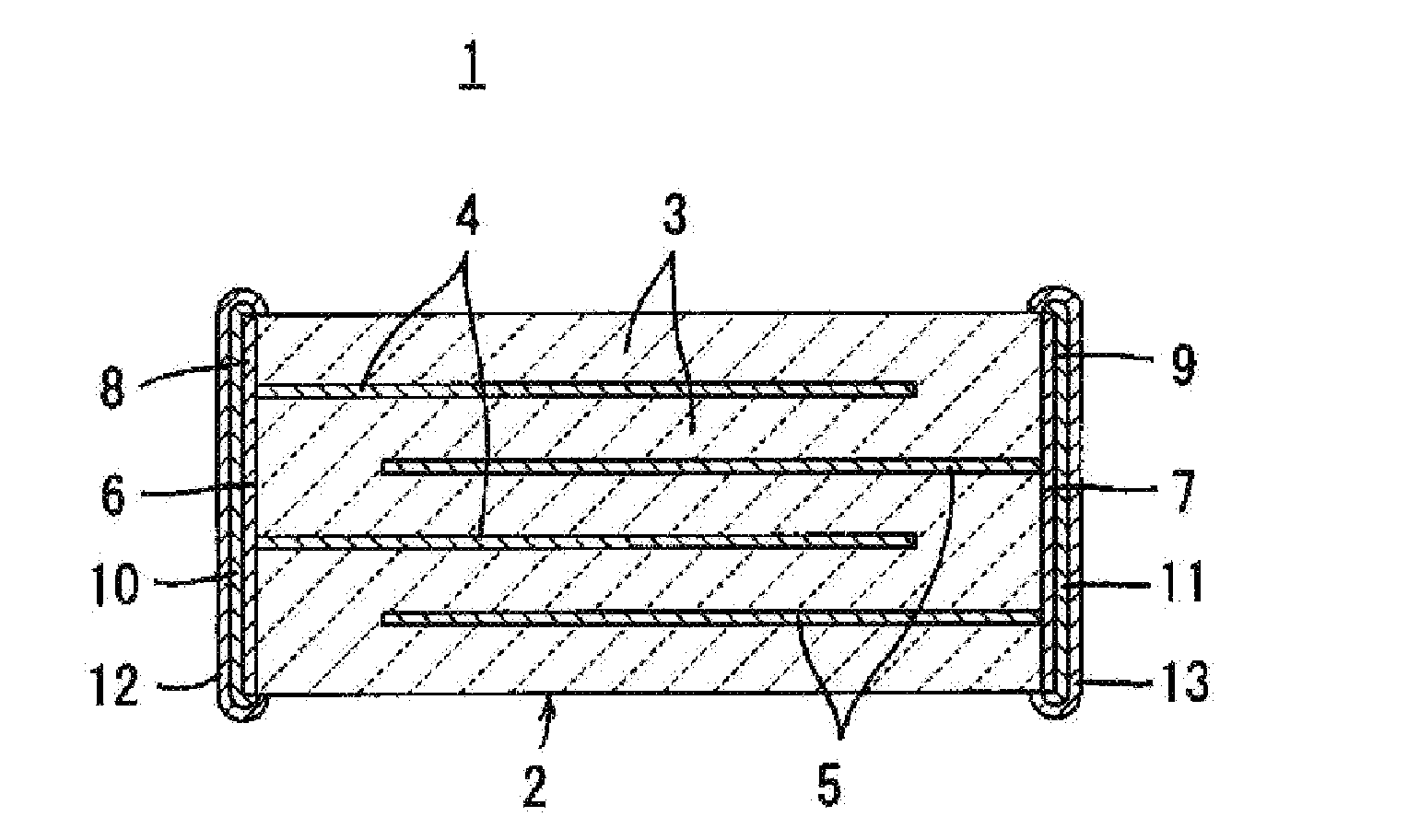
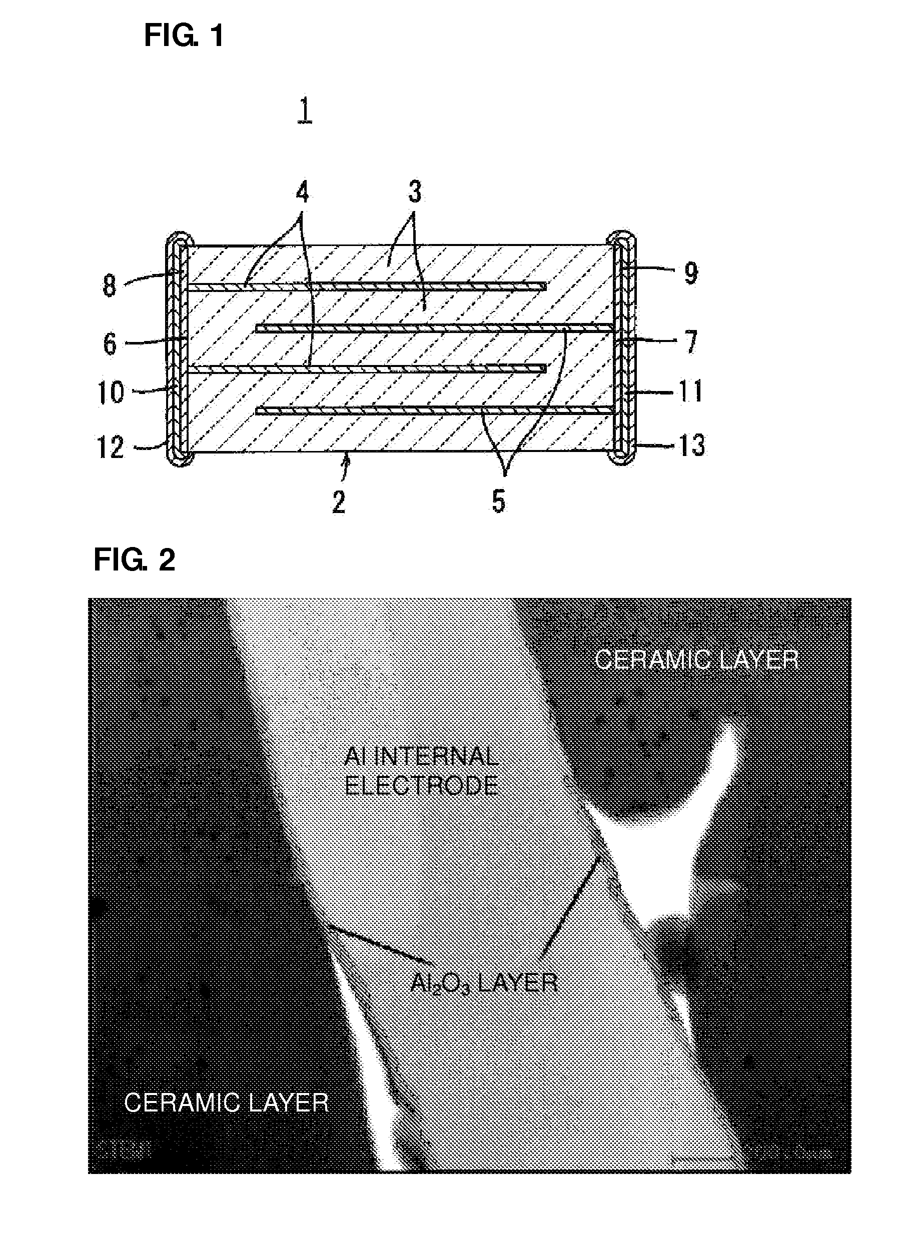
[0035]The present example is intended to examine the dependence on the presence or absence and thickness of an Al2O3 layer in laminated ceramic electronic components which have six different types of ceramic compositions and Al internal electrodes.

[0036]First, a BaTiO3 powder was prepared as a main constituent of a ceramic, and Bi2O3, CuO, B2O3, BaO, and SiO2 powders were prepared as accessory constituents. These powders were mixed so as to satisfy the six types of content rates shown in Table 1, thereby providing six types of ceramic raw materials.

TABLE 1BaTiO3Bi2O3CuOB2O3BaOSiO2Composition(mol %)(mol %)(mol %)(mol %)(mol %)(mol %)1-190910001-290730001-390800201-490802001-55025000251-6503500015

[0037]An ethanol-based organic solvent and a polyvinyl butyral based binder were added to each of these ceramic raw materials, followed by wet mixing in a ball mill, to obtain ceramic slurries. The ceramic slurries were subjected to sheet forming to obtain ceramic green sheets.

[0038]Next, an ...

example 2

[0047]The present example is intended to examine the influence in the case of changing internal electrodes from Ni to Al in a certain dielectric ceramic material.

[0048]First, a ceramic raw material represented by the composition formula 100(Ba0.95Ca0.05)1.01TiO3+0.2Dy2O3+0.1 MnO+0.6MgO+2.0SiO2+0.5Li2O was prepared.

[0049]This ceramic raw material was used to obtain ceramic green sheets in the same way as in Example 1. In parallel, an Al paste including an Al metal powder and an organic vehicle and a Ni paste including a Ni metal powder and an organic vehicle were prepared.

[0050]Next, the Al paste was applied by screen printing onto the ceramic green sheets to form Al paste layers. The ceramic green sheets with the Al paste applied were stacked so that the sides to which the Al paste layers were drawn were alternated, followed by pressure bonding, thereby providing a raw laminate. In the same way, a raw laminate was obtained in the case of using the Ni paste.

[0051]The raw laminates we...

example 3

[0057]The present example is intended to evaluate laminates including Al internal electrodes with a variety of compositions as ceramic compositions for firing at low temperatures.

[0058]First, respective starting raw materials were mixed so as to satisfy the compositions shown in Table 4, thereby providing ceramic raw materials of six types of compositions, raw materials 3-1 to 3-6.

TABLE 4RawMate-Bi2O3SiO2CaZrO3B2O3PbOAl2O3TeO2rial(mol %)(mol %)(mol %)(mol %)(mol %)(mol %)(mol %)3-165353-275253-330703-410903-52983-61.5971.5

[0059]The ceramic raw materials were used to obtain ceramic green sheets in the same way as in Example 1. In parallel, an Al paste including an Al metal powder and an organic vehicle, a Ni paste including a Ni metal powder and an organic vehicle, and a Cu paste including a Cu metal powder and an organic vehicle were prepared.

[0060]Next, the Al paste was applied by screen printing onto the ceramic green sheets from the raw material 3-1 to 3-4 to form Al paste layers...


PUM

PropertyMeasurementUnit
Temperatureaaaaaaaaaa
Pressureaaaaaaaaaa

Abstract

A laminated ceramic electronic component has a variety of superior mechanical properties and electrical properties, including a high degree of freedom in the design for ceramic materials, and can be manufactured at low cost and with a low percentage of defective products. The laminated ceramic electronic component includes a laminate including a plurality of stacked ceramic layers and a plurality of internal electrodes containing Al as a main constituent, the internal electrodes being arranged along specific interfaces between the ceramic layers, and external electrodes located on an outer surface of the laminate, wherein surface layer sections of the internal electrodes include an Al2O3 layer.

Description

BACKGROUND OF THE INVENTION[0001]1. Field of the Invention[0002]The present invention relates to a laminated ceramic electronic component typified by a laminated ceramic capacitor, for example, and more particularly, relates to a laminated ceramic electronic component including an internal electrode containing Al as its main constituent.[0003]2. Description of the Related Art[0004]With reference to FIG. 1, a laminated ceramic capacitor 1 will be described first which is a typical example of a laminated ceramic electronic component.[0005]The laminated ceramic capacitor 1 includes a laminate 2 composed of a plurality of stacked dielectric ceramic layers 3 and a plurality of internal electrodes 4 and 5 formed along specific interfaces between the dielectric ceramic layers 3.[0006]First and second external electrodes 8 and 9 are formed in different positions from each other on the outer surface of the laminate 2. The laminated ceramic capacitor 1 shown in FIG. 1 has the first and second...

Claims


Application Information

Patent Timeline
IPC IPC(8): H01G4/005B29C65/02
CPCH01C7/008H01C7/18H01G4/0085H01L41/0477H01G4/30H01L41/0471H01G4/1209H10N30/871H10N30/877H01G4/12H01G4/224
Inventor SUZUKI, SHOICHIROBANNO, KOICHIOTSUKA, MASAHIRONAKAMURA, MASANORIJONO, SEIICHIKANZAKI, TAISUKESHIOTA, AKIHIRO
Owner MURATA MFG CO LTD
Why Eureka
Try Eureka