
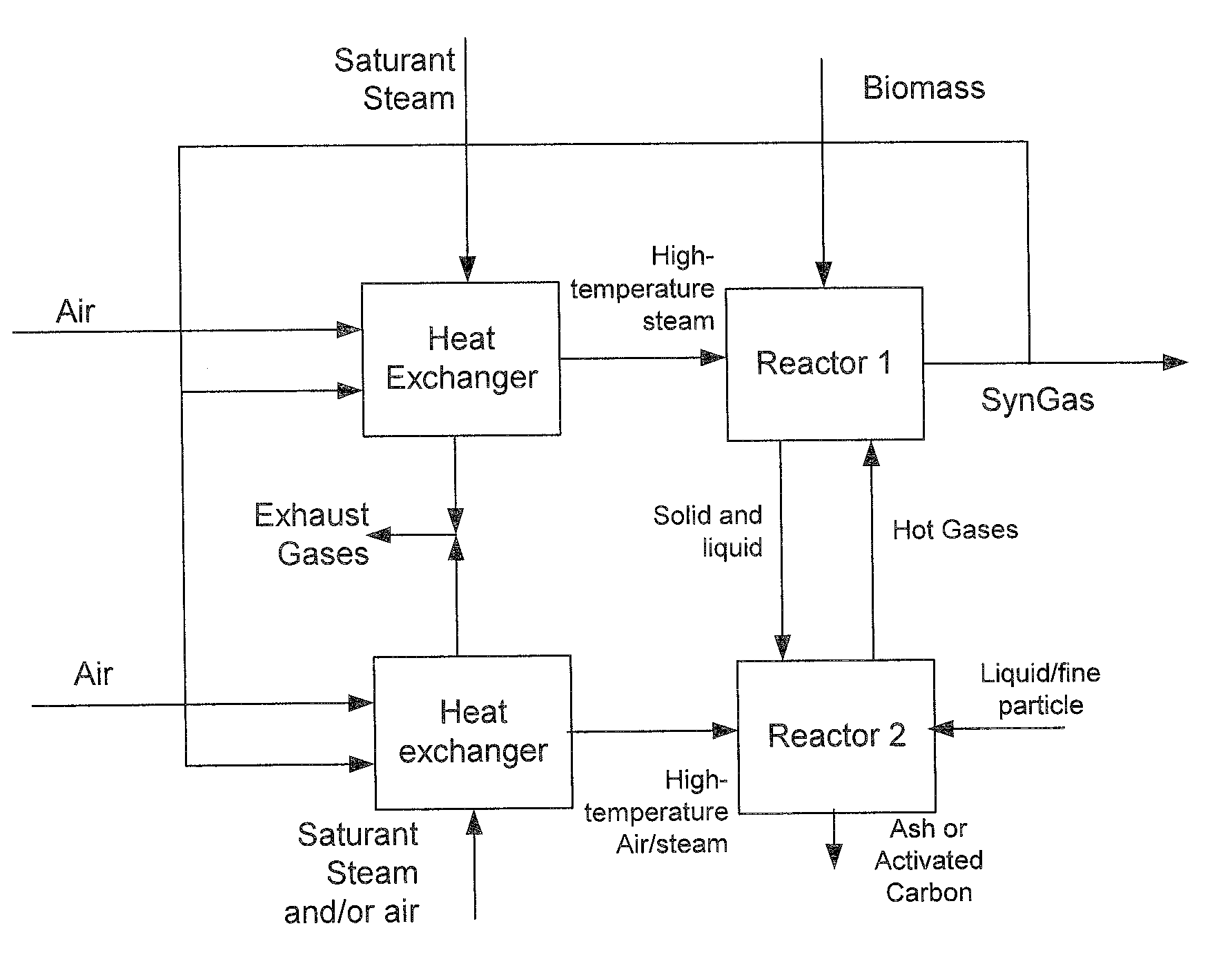
Two-stage high-temperature preheated steam gasifier

a gasifier and high-temperature technology, applied in the direction of gasification process details, special form destructive distillation, inorganic chemistry, etc., can solve the problems of low caloric value, small partial pressure, and unfavorable other valuable gasification reactions, so as to minimize the need for separation of by-products and keep the undesired dilution of gaseous products to a minimum

Inactive Publication Date: 2011-04-07
BOSON ENERGY
View PDF12 Cites 27 Cited by
  • Summary
  • Abstract
  • Description
  • Claims
  • Application Information

AI Technical Summary

Benefits of technology

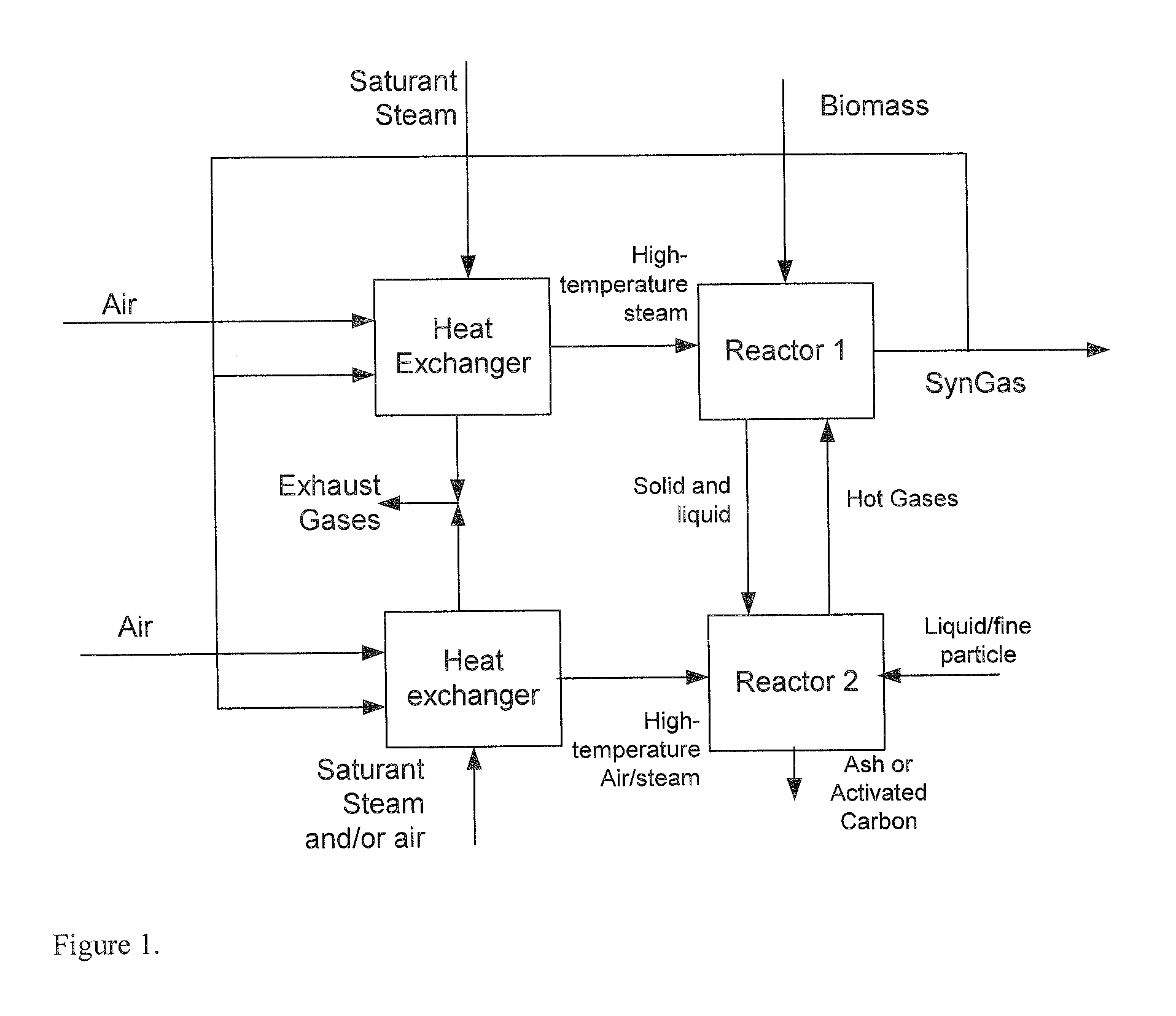
[0031]In another a preferred embodiment of the process externally generated preheated steam having a temperature of at least 700° C. is also fed into the second stage reactor. With this embodiment internal combustion, also referred to as partial combustion or oxidation, in the gasifier can be kept to a minimum, since the required energy is provided externally. Consequently, supply of air or oxygen is not required for heat generation by internal combustion in this embodiment. Also, when air or oxygen is not being fed to the second reactor the yield of activated carbon can be maximised.
[0033]In a further preferred embodiment of the process pure oxygen is used (instead of air). In this embodiment the process can be used for industrial purposes. Also, the need for separation of by-products is minimized, and undesired dilution of the gaseous product is kept to a minimum.

Problems solved by technology

By means of the technology, the non-combustible gas, CO2, is produced, and, as it is not removed, it leads to a diluted syngas, and the LCV (low caloric value, a measure for the burning value of the dry gas mass) of the produced syngas becomes limited.
Moreover, the presence of CO2 resulting from partial combustion (oxidation) leads to a small partial pressure of other gas species, which is not favorable for other valuable gasification reactions, such as for example, the water-gas shift reaction.
Thus, the hydrogen content in the syngas will be negatively affected.
The use of enhanced oxygen gas in the method will obviously increase the operation cost of the method.
However, because of the limited heat in the steam, the problems associated with steam-only gasification include low achievable reaction temperatures, i.e. typically less than about 815° C., where long residence times and high energy consumption prevail.
However, the injection of secondary air will not only increases the diluents contents, notably nitrogen, but will also reduce the combustible contents generated from gasification.
This results in a decrease of LCV of the fuel gas produced.
Furthermore, injection of secondary air makes it hard to control the composition of the produce gas.
U.S. Pat. No. 6,960,234, mentioned above, also states that fixed-bed gasification requires coarse fuels (typically ¼″ to 2″ in diameter, and that limiting technical features of fixed-bed gasification include: tar and oil carry over with the syn gas; difficulty in using coal / fuel fines because they clog the void space between the coarse fuels in the fixed bed; and difficulty in using liquid hydrocarbon feedstocks.

Method used


Image

  • Two-stage high-temperature preheated steam gasifier
  • Two-stage high-temperature preheated steam gasifier
  • Two-stage high-temperature preheated steam gasifier

Examples


example 1

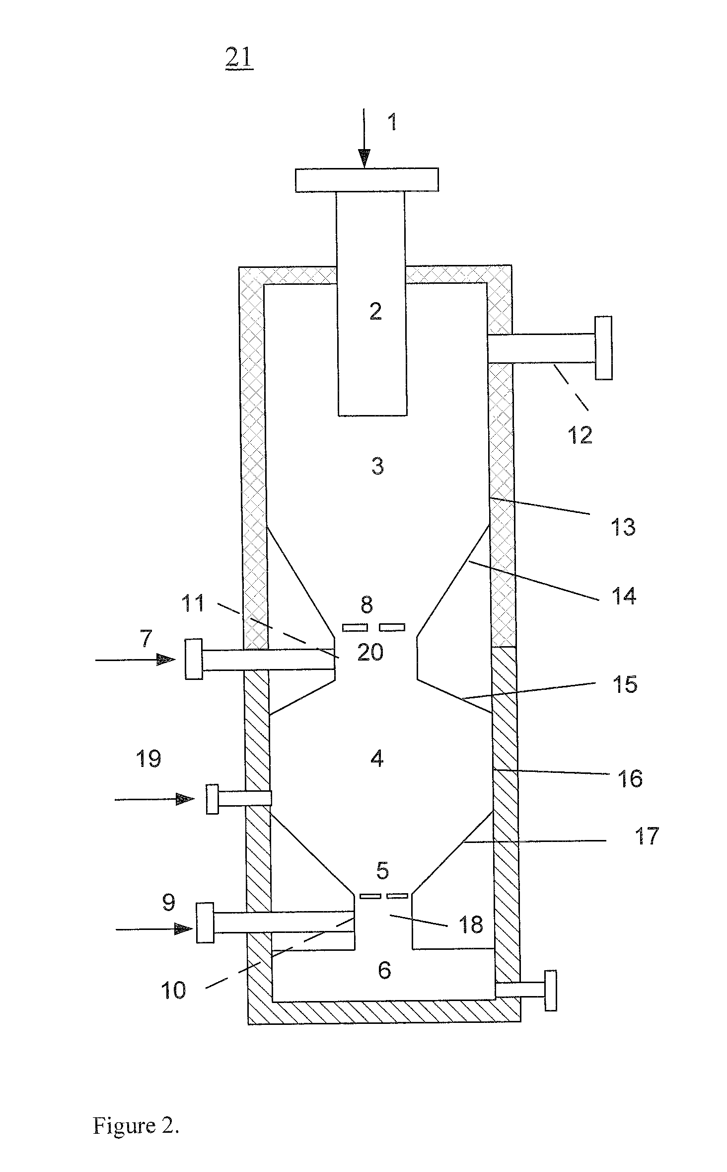
[0074]97 kg / h of wood pellets 1 with a diameter around 8 mm is feed into the first reactor from the inlet 2 by weight at room temperature (15° C.). The properties of the wood pellets are shown in Table 1.

TABLE 1Proximate and ultimate analysis of the feedstocks usedProximate analysisWood Pellets (WP)Total Moisture (SS187170)8%Ash content (SS-187171)0.5-0.6% (dry)LHV (SS-ISO562)17.76 MJ / kg (as received)Volatile matter (SS-ISO)84% (dry)Density630-650 kg / m3Ultimate analysis (dry compositions)Wood PelletsSulphur (SS-187177)S0.01-0.02%Carbon (Leco-600)C50%Hydrogen (Leco-600)H6.0-6.2%Nitrogen (Leco-600)NOxygen (Calculated)O43-44%Ash fusion temperatures (oxidizing conditions)Wood PelletsInitial deformation, IT1350-1400° C.Softening, ST1450-1500° C.Hemispherical, HT   1500° C.Fluid temperature, FT1500-1550° C.

example 2

[0075]A 60 kg / h of Refuse Derived Fuel (RDF), a pellet formed fuel made from paper fiber mixed with other substances such as fabric fiber, wood chips and plastics, was used as feedstock, with a diameter of about 8 mm, and was feed into the first reactor 3 from the top 1 by weight, i.e. by the action of gravity, at room temperature (15° C.). The properties of the RDF pellets are shown in Table 2.

TABLE 2Proximate and ultimate analysis of the RDF feedstock usedProximate analysisRefused Derived Fuel (RDF)Total Moisture (SS187170)2.9%Ash content (SS-187171)6.0% (dry)LHV (SS-ISO562)26.704 MJ / kg (as received)Volatile matter (SS-ISO)84.4% (dry) Density472 kg / m3Ultimate analysis (dry compositions)RDFSulphur (SS-187177)S19 0.09%Carbon (Leco-600)C63.3%Hydrogen (Leco-600)H 8.9%Nitrogen (Leco-600)N 0.3%Oxygen (Calculated)O20.95% Ash fusion temperatures (oxidizing conditions)RDFInitial deformation, IT1210° C.Softening, ST1220° C.Hemispherical, HT1230° C.Fluid temperature, FT1240° C.


PUM


Abstract

A gasifier combines two reactors using externally generated preheated high temperature steam injection into the first reactor, where the heating demand for gasification is supplied by the sensible energy from the steam. The gasifier can produce a medium and higher LCV syngas. The first reactor is a fixed bed gasification section where the coarse feedstock is gasified, and the second reactor is an entrained-bed gasification section where the liquid and fine feedstock is gasified. Solid coarse feedstock is devolatilized in the first fixed bed reactor of the gasifier with high-temperature steam, and subsequently, in the second reactor subjected to a higher temperature sufficient to crack and destroy tars and oils. Activated carbon may be formed as co-product. The gasifier may be used with various solid and liquid feedstocks. The gasifier is capable of gasifying such different feedstocks simultaneously.

Description

FIELD OF THE INVENTION[0001]The present invention generally relates to a two-stage high-temperature steam gasifier for producing synthesis gas and, optionally, activated carbon, from a coarse carbonaceous feedstock, and more particularly to a gasifier capable of simultaneously gasifying a coarse solid carbonaceous feedstock and a fine solid carbonaceous feedstock or a liquid carbonaceous feedstock. The present invention also relates to a process of gasifying a coarse carbonaceous feedstock using a two-stage gasifier having two reactors in order to produce synthesis gas, optionally together with activated carbon, wherein no oxygen is fed to the first stage reactor, but only preheated steam having a temperature of at least 700° C.BACKGROUND OF THE INVENTION[0002]Gasification is a high-temperature thermal decomposition process of converting a solid feedstock, such as solid coal, petroleum coke, biomass, and / or solid waste, a liquid feedstock, such as black liquid oil, or a gaseous feed...

Claims


Application Information

Patent Timeline
IPC IPC(8): C10J3/20C10J3/02C10B49/02
CPCC10B49/06C10J3/485C10J3/14C10J3/16C10J3/36C10J3/721C10J2200/09C10J2200/152C10J2300/0903C10J2300/0916C10J2300/092C10J2300/094C10J2300/0946C10J2300/0956C10J2300/0973C10J2300/1637Y02E50/14C10B53/02Y02P20/145Y02P20/129Y02E50/10
Inventor BLASIAK, WLODZIMIERZYANG, WEIHONG
Owner BOSON ENERGY
Learn More