
Chemical sensor employing resonator-enhanced forbidden-light collection

a raman scattering and chemical sensor technology, applied in the field of chemical sensors, can solve the problems of raman signal degradation, reduced quality factor (q), and often too weak raman signal for very sensitive chemical detection

Inactive Publication Date: 2011-04-07
PIPINO ANDREW C R
View PDF21 Cites 13 Cited by
  • Summary
  • Abstract
  • Description
  • Claims
  • Application Information

AI Technical Summary

Benefits of technology

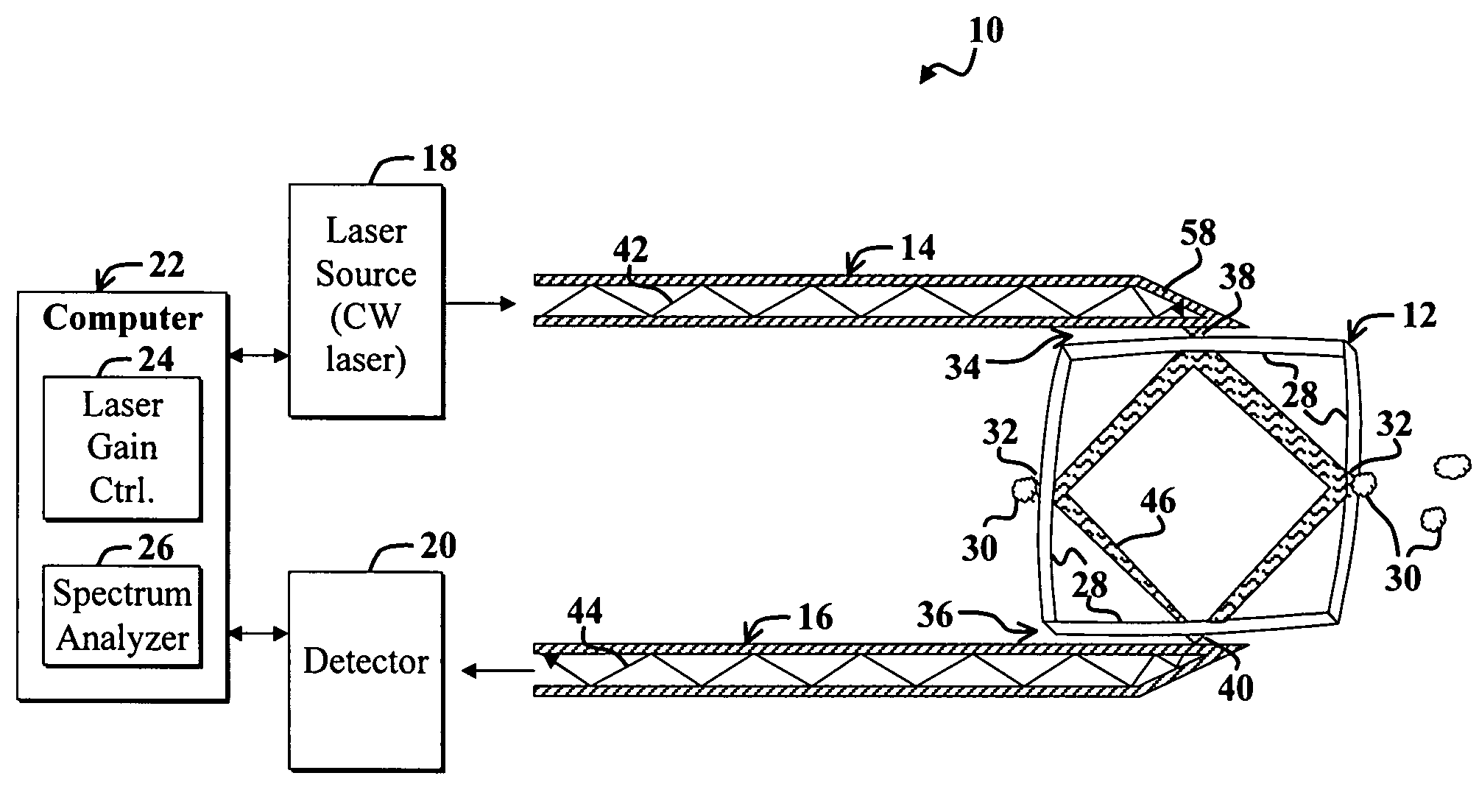
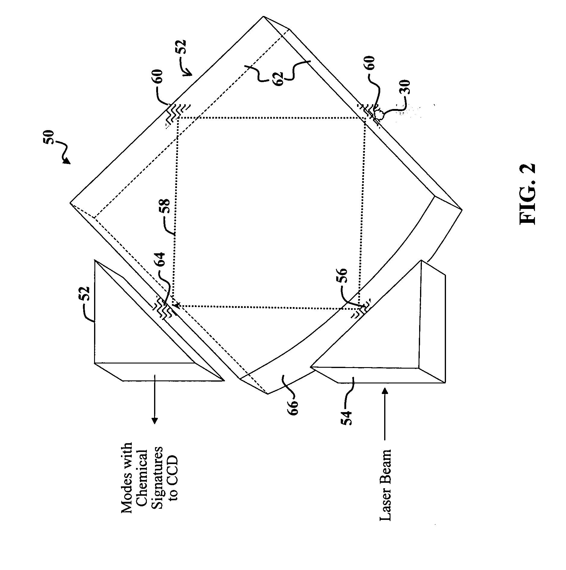
[0016]Optical modes propagating within the dielectric resonator are substantially confined by total internal reflection by one or more sidewalls of the dielectric resonator. The dielectric resonator is dimensioned to ensure that a plurality of modes propagate within the dielectric resonator. Plural modes are chosen to increase the probability that the Raman signal will couple to one or more of the plural modes propagating within the dielectric resonator. The plural modes are said to optimize a photon density of states to maximize coupling of Raman-scattered electromagnetic energy to modes propagating within the dielectric resonator.
[0019]The novel design of certain embodiments discussed herein is facilitated by use of a stable dielectric resonator to provide well-defined, high-Q optical modes, which can be efficiently excited by an appropriate light source.
[0020]The novel design of certain embodiments discussed herein is further facilitated by use of a dielectric resonator (e.g., silica or glass) that sustains optical modes by total-internal reflection, such that the near field energy, also called evanescent waves or forbidden light, can be used for chemical sensing. The benefits of the evanescent wave are multi-fold. Specifically, for double resonance enhancement of Raman-scattered electromagnetic energy, the incident near field energy on a species yields a Raman signal that is resonant with one or more modes within the resonator. The resonator thereby acts to efficiently collect the Raman-scattered light. Coupling between the Raman emission and the modes of the resonator facilitates converting near field Raman-scattered energy into far field energy propagating within the resonator. The resulting Raman-scattered energy within the resonator may be extracted and analyzed to facilitate characterization of the species, i.e., material sample. Use of Raman spectroscopy as disclosed herein can reveal small changes in chemical composition of complex mixtures through subtle spectral variations.
[0021]A dielectric resonance structure as disclosed herein enables significant Raman signal enhancements, which may be larger than enhancements achieved via conventional metallic SERS structures. Such significant Raman signal enhancement is due in part to the very high-Q resonator modes enabled by smaller optical losses in the accompanying dielectric resonator as compared to metal SERS devices. In addition, use of dielectric materials will facilitate cost-effective mass production and improve reproducibility in comparison with conventional SERS-based chemical detectors.
[0022]Certain embodiments disclosed herein may obtain Raman vibrational spectra via a fixed wavelength, narrow bandwidth, and low-power diode laser source such as an extended cavity diode laser. This may further facilitate construction of compact devices, since large high-power tunable laser sources may be unnecessary.

Problems solved by technology

Unfortunately, the resulting Raman signal often remains too weak for very sensitive chemical detection.
Unfortunately, metal surfaces required for plasmon-based enhancement of Raman signals can be susceptible to heating and resulting reduced Quality factor (Q).
Furthermore, nano structures used to texture a metal surface may be susceptible to damage or degradation, which can degrade the Raman signal.
In addition, certain molecules may exhibit unknown electronic resonance when in proximity to such metal surfaces, which can complicate accurate chemical detection and selectivity, such as by resulting in detection errors.
Furthermore, construction of the metal surfaces and accompanying nano structures may be cost-prohibitive for certain applications, and such devices may be difficult to accurately reproduce.
In addition, SERS chemical detectors may not be suitable for applications where the species cannot be effectively bound to the metal surfaces thereof.
Such factors can limit mass fabrication and commercial viability of SERS devices for sensitive and selective chemical detection.

Method used


Image

  • Chemical sensor employing resonator-enhanced forbidden-light collection
  • Chemical sensor employing resonator-enhanced forbidden-light collection
  • Chemical sensor employing resonator-enhanced forbidden-light collection

Examples


Embodiment Construction

[0030]While embodiments are described herein with reference to particular applications, it should be understood that the embodiments are not limited thereto. Those having ordinary skill in the art and access to the teachings provided herein will recognize additional modifications, applications, and embodiments within the scope thereof and additional fields in which the present invention would be of significant utility.

[0031]For clarity, various well-known components, such as power supplies, mounting systems, and so on, have been omitted from the figures. However, those skilled in the art with access to the present teachings will know which components to implement and how to implement them to meet the needs of a given application. Furthermore, the figures are not necessarily drawn to scale.

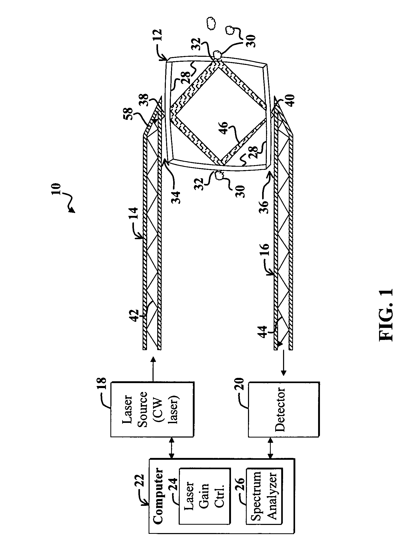
[0032]FIG. 1 is a diagram of a chemical sensing system 10 according to a first example embodiment. The example system 10 includes a stable dielectric resonator 12, which represents a cavity bounded...


PUM


Abstract

A chemical sensor that includes, in one example embodiment, a dielectric resonator, wherein a material sample to be characterized is positioned a species to be detected, wherein the species is positioned near a surface of the resonator so that evanescent electromagnetic energy emanating from the surface causes Raman scattering from the species. The resonator is adapted to support modes propagating within the resonator, wherein the modes are adapted to yield the evanescent electromagnetic energy and to couple Raman-scattered electromagnetic energy back into one or more of the modes. In a more specific embodiment, the dielectric cavity represents a stable optical resonator. An input coupling optic couples input electromagnetic energy into the dielectric cavity via photon tunneling across a gap between the input coupling optic and the dielectric cavity. A distance across the gap is approximately one wavelength or larger, wherein the wavelength corresponds to a wavelength of the input electromagnetic energy. An output coupling optic is adapted to couple one or more modes within the dielectric cavity that contain electromagnetic energy corresponding to the Raman-scattered electromagnetic energy, and to provide an output signal in response thereto.

Description

BACKGROUND OF THE INVENTION[0001]1. Field of Invention[0002]This invention relates to chemical sensors. Specifically, the present invention relates to spectroscopic chemical sensors employing Raman scattering.[0003]2. Description of the Related Art[0004]Chemical sensors are employed in various demanding applications including industrial process monitoring, environmental monitoring, national security (e.g., chemical weapons detection), defense (e.g., munitions-condition monitoring), medical diagnostics (e.g., disease characterization), drug delivery monitoring, biosensing (e.g., virus detection), industrial process control, product quality monitoring, and scientific research, and so on. Such applications often demand compact, versatile, selective, highly sensitive chemical detectors.[0005]For the purposes of the present discussion, a chemical sensor, also called a chemical detector, may be any device that is adapted to facilitate characterizing a substance, such as by detecting exist...

Claims


Application Information

Patent Timeline
IPC IPC(8): G01J3/44
CPCG01J3/44G01N21/7746G01N21/65
Inventor PIPINO, ANDREW C.R.
Owner PIPINO ANDREW C R
Learn More