Gas deacidizing method using an absorbent solution with vaporization and/or purification of a fraction of the regenerated absorbent solution

a technology of absorbent solution and gaseous effluent, which is applied in the preparation of gaseous fuels, hydrogen sulfides, urea derivatives, etc., can solve the problems of liquid-liquid separation problems, oxygen presence can generate other degradation reactions, foaming problems, etc., to reduce the amount of solution, and reduce the effect of oxygen

Active Publication Date: 2011-04-07
INST FR DU PETROLE
View PDF3 Cites 39 Cited by
  • Summary
  • Abstract
  • Description
  • Claims
  • Application Information

AI Technical Summary

Benefits of technology

[0026]Separation allows to optimize the operations carried out on the regenerated absorbent solution. On the one hand, separation of the regenerated absorbent solution into two fractions allows to carry out vaporization by the reboiler of a fraction of the absorbent solution, preferably containing a limited reactive compound concentration in relation to the absorbent solution, thus limiting their degradation. On the other hand, separation allows to reduce the amount of solution to be treated in order to remove the non-regeneratable salts and thus to reduce the costs linked with the elimination of the non-regeneratable salts. Finally, separation allows to eliminate the degradation products by carrying out a specific and suitable purification for each fraction.

Problems solved by technology

However, thermal regeneration of the absorbent solution favours degradation of the organic compounds contained in the absorbent solution.
Furthermore, in the case of combustion fumes treatment, for example thermal power plant fumes, the presence of oxygen can generate other degradation reactions.
Thus, they can pose foaming problems, or liquid-liquid separation problems by stabilizing the phases in form of an emulsion.
These liquid-liquid separation problems can be encountered when using the method described in document FR-2,898,284 or in the case of gas treatment where the liquid hydrocarbons are eliminated from the absorbent solution by liquid-liquid separation, after the absorption column.
Furthermore, non-regeneratable salts are known to be responsible for corrosion and foaming problems within the units.
Besides, when the reactive compounds are weakly volatile, it may be difficult to vaporize the absorbent solution at atmospheric pressure.
Despite this distillation temperature decrease, degradations still may occur during this purification operation.
These purification operations have a quite significant impact on the operating costs of the unit.
Finally, since the purification operations through ion exchange or distillation do not allow to remove all of the organic degradation products, it may be necessary to periodically renew all of the absorbent solution when its performances are too low.
The costs associated with the purchase of a new solvent feed and with the elimination of the degraded absorbent solution feed are high.

Method used


Image

  • Gas deacidizing method using an absorbent solution with vaporization and/or purification of a fraction of the regenerated absorbent solution
  • Gas deacidizing method using an absorbent solution with vaporization and/or purification of a fraction of the regenerated absorbent solution
  • Gas deacidizing method using an absorbent solution with vaporization and/or purification of a fraction of the regenerated absorbent solution

Examples


Embodiment Construction

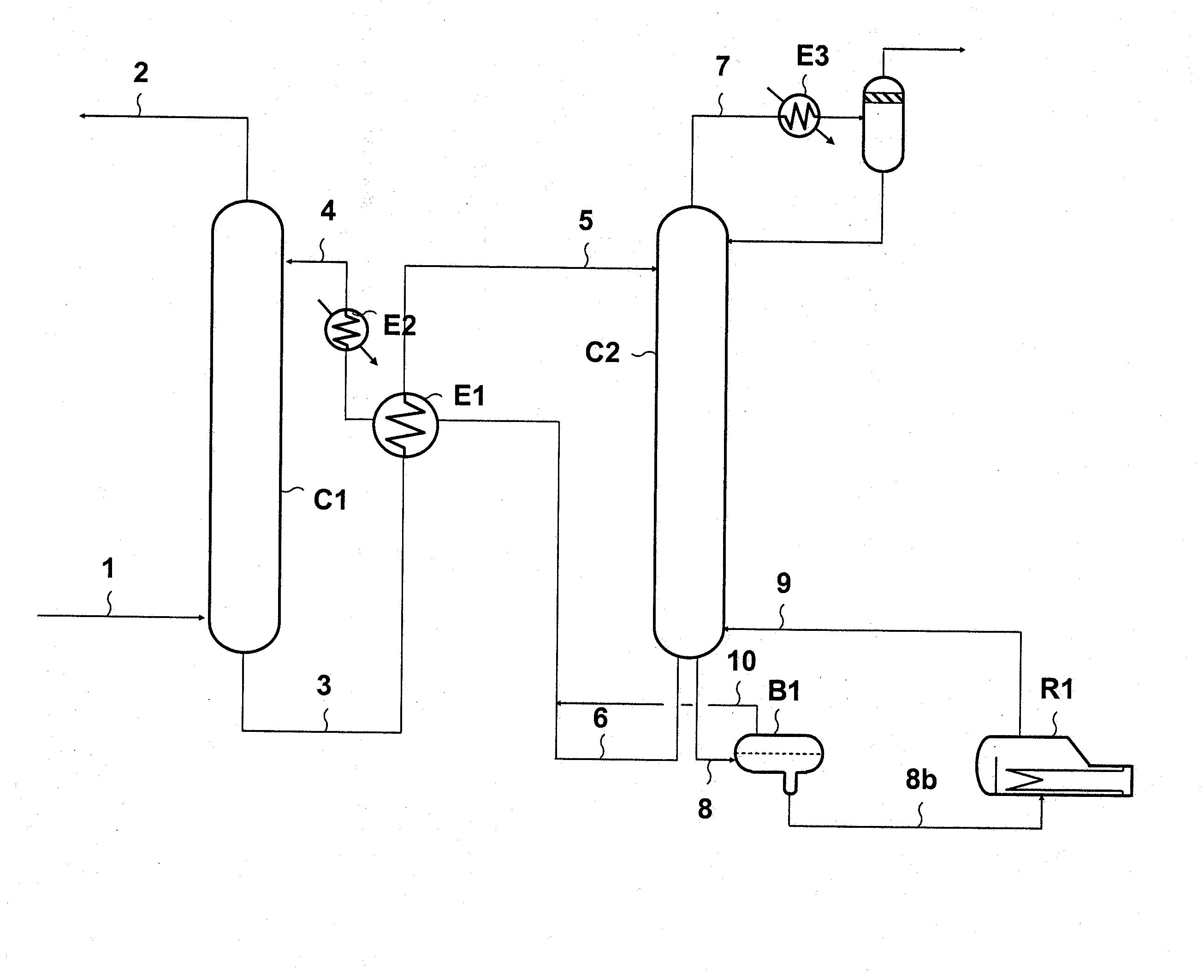
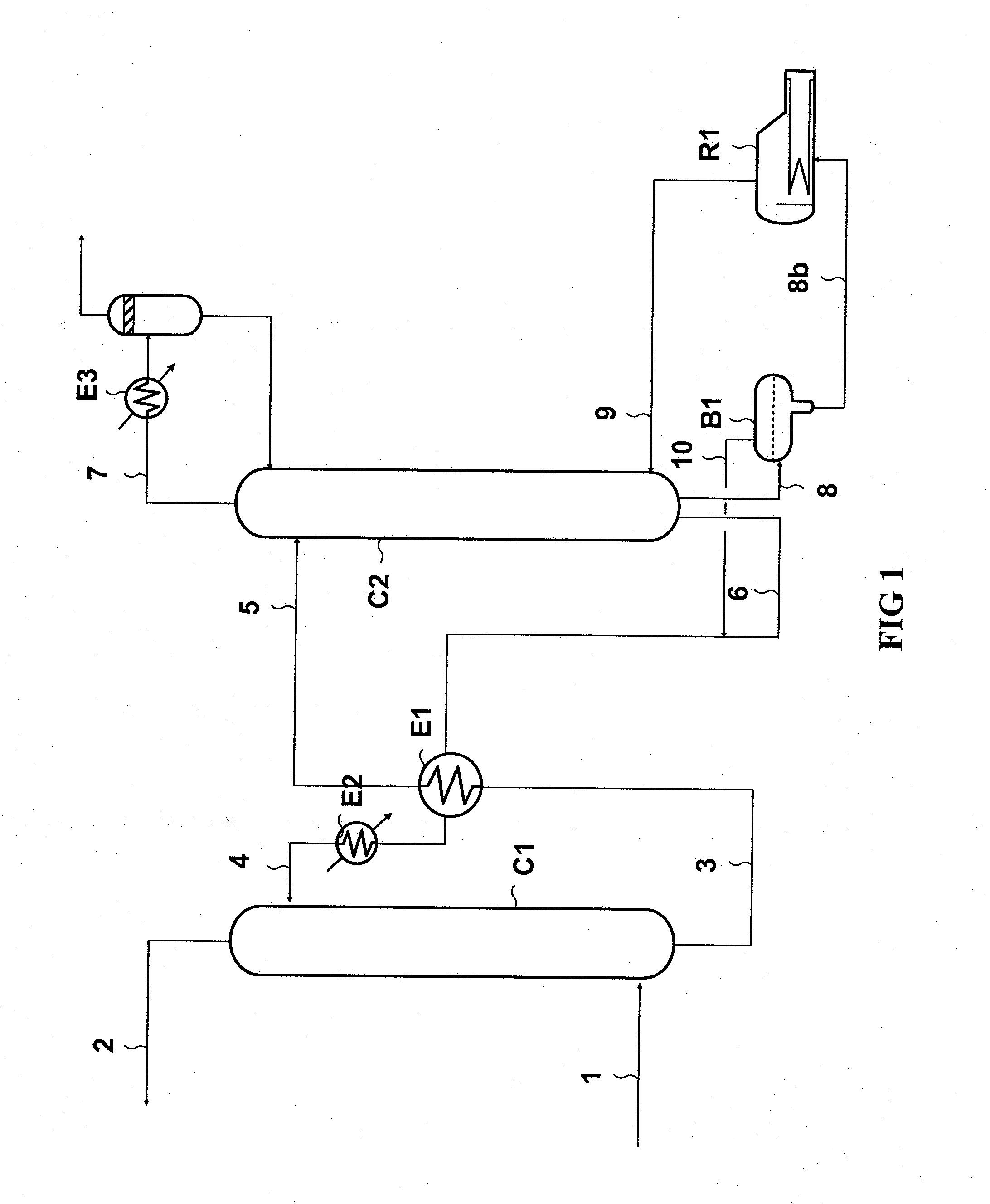
[0032]With reference to FIG. 1, the gaseous effluent to be deacidized circulating in line 1 is contacted in absorption column C1 with the absorbent solution flowing in through line 4. Column C1 is equipped with gas / liquid contacting internals, for example distillation trays, a random or a stacked packing.

[0033]The deacidizing method according to the invention can be applied to various gaseous effluents. For example, the method allows to decarbonate combustion fumes, to deacidize natural gas or a Claus tail gas. The method also allows to remove the acid compounds contained in synthesis gas, in conversion gas in integrated coal or natural gas combustion plants, and in the gas resulting from biomass fermentation.

[0034]In column C1, the reactive compounds of the absorbent solution react with the acid compounds so as to form a salt soluble in the solution. The gas depleted in acid compounds is discharged from C1 through line 2. The absorbent solution enriched in acid compounds, in form o...


PUM

PropertyMeasurementUnit
temperatureaaaaaaaaaa
wt. %aaaaaaaaaa

Abstract

The gaseous effluent to be treated is contacted in column C1 with an absorbent solution selected for its property of forming two separable phases when it is heated. The regenerated absorbent solution is separated into two phases in drum B1; a fraction rich in water and a fraction rich in reactive compounds.Separation allows to optimize the operations performed on the regenerated absorbent solution. On the one hand, separation allows to carry out vaporization, through reboiler R1, of a fraction of the absorbent solution, preferably containing a limited reactive compound concentration in relation to the absorbent solution, thus limiting their degradation. On the other hand, separation of the phases allows to reduce the amount of solution to be treated in order to remove the non-regeneratable salts and thus to reduce the costs linked with their elimination. Finally, separation allows to eliminate the degradation products by carrying out a specific and suitable purification for each phase.The method can be applied to combustion fumes decarbonation and to natural gas or synthesis gas deacidizing.

Description

FIELD OF THE INVENTION[0001]The present invention relates to the field of deacidizing a gaseous effluent by means of an absorbent solution.[0002]The method according to the Invention allows to remove acid compounds such as carbon dioxide (CO2) and hydrogen sulfide (H2S) contained in a gaseous effluent. It can be applied for treating a natural gas, a synthesis gas or fumes from a combustion process.BACKGROUND OF THE INVENTION[0003]Document FR-2,898,284 aims to use a demixing absorbent solution having the property of splitting up when said absorbent solution laden with acid compounds is heated. The absorbent solution is contacted with the gas to be deacidized. During regeneration, the solution divides into two phases: a fraction rich in acid compounds and a fraction poor in acid compounds. Thus, document FR-2,898,284 aims to regenerate by distillation only the fraction that is enriched in acid compounds in order to minimize the energy required for regeneration of the absorbent solutio...

Claims


Application Information

Patent Timeline
Patent Type & Authority Applications(United States)
IPC IPC(8): B01D53/52B01D53/62C01B32/50
CPCB01D53/1425Y02C10/06B01D53/1468B01D53/1475B01D53/1493B01D53/62B01D53/78B01D2257/304B01D2257/504C01B3/52C01B31/20C01B2203/0475C01B2203/0485C10L3/10C10L3/102F23J15/04F23J2219/40Y02C10/04B01D53/1462C01B32/50Y02C20/40Y02E20/32Y02P20/151
Inventor BOUILLON, PIERRE-ANTOINEJACQUIN, MARC
Owner INST FR DU PETROLE
Why Eureka
Try Eureka