Antithrombogenic surface

a technology of antithrombosis and surface, applied in the field of laminated films, can solve the problems of deterioration of performance during use of medical devices, clinical problems, complicated control of production and operation, etc., and achieve the effects of low thickness, favorable coating, and high antithrombosis

Inactive Publication Date: 2011-04-14
KANEKA CORP +1
View PDF4 Cites 6 Cited by
  • Summary
  • Abstract
  • Description
  • Claims
  • Application Information

AI Technical Summary

Benefits of technology

[0022]The films of the present inventions (1) to (8), which have alternately laminated polymer layers of polymer compounds different in electrification state and also fine spatial asperities formed on the surface, are laminated films having a surface unprecedentedly higher in antithrombogenicity. Such an antithrombogenic laminated film can be prepared, for example, by alternate adsorption method of depositing polymer compounds different in electrification state alternately, and it is possible to make the film very thin and yet show spatial asperities (texture structure), by adjustment of the concentration, pH value and adsorption period of the polymers used and to provide an antithrombogenic surface having unprecedentedly low thickness and favorable coatability. The texture is regular or irregular “pattern” inherently present on the surface of an object, and in the present invention, a pattern irregular but approximately uniform in size, which is formed by the spatial asperities, is called a three-dimensional texture structure.
[0023]The invention (9) provides a medical device having a surface unprecedentedly higher in antithrombogenicity. Because it is possible to form the antithrombogenic laminated film even on the surface of a very thin and fine structure for example by the alternate adsorption method above, it is possible to form an antithrombogenic surface on medical devices that could not be designed, because of difficulty in forming the antithrombogenic surface.
[0024]The present invention (10) provides a filter having a surfac

Problems solved by technology

These medical devices, when brought into contact with blood, may cause thrombosis by coagulation of the blood on the surface, leading to deterioration in performance during use of the medical devices and further causing clinical problems.
However, use of a physiologically active substance, such as heparin, is disadvantageous in many points including that control of production and operation are complicated, applicable surfaces are limited, and the physiologically active substance loses its action, as they are inactivated.
However, the surface of the microphase-separated structure should be controlled in a favorably phase-separated state f

Method used


Image

  • Antithrombogenic surface
  • Antithrombogenic surface
  • Antithrombogenic surface

Examples


example 1

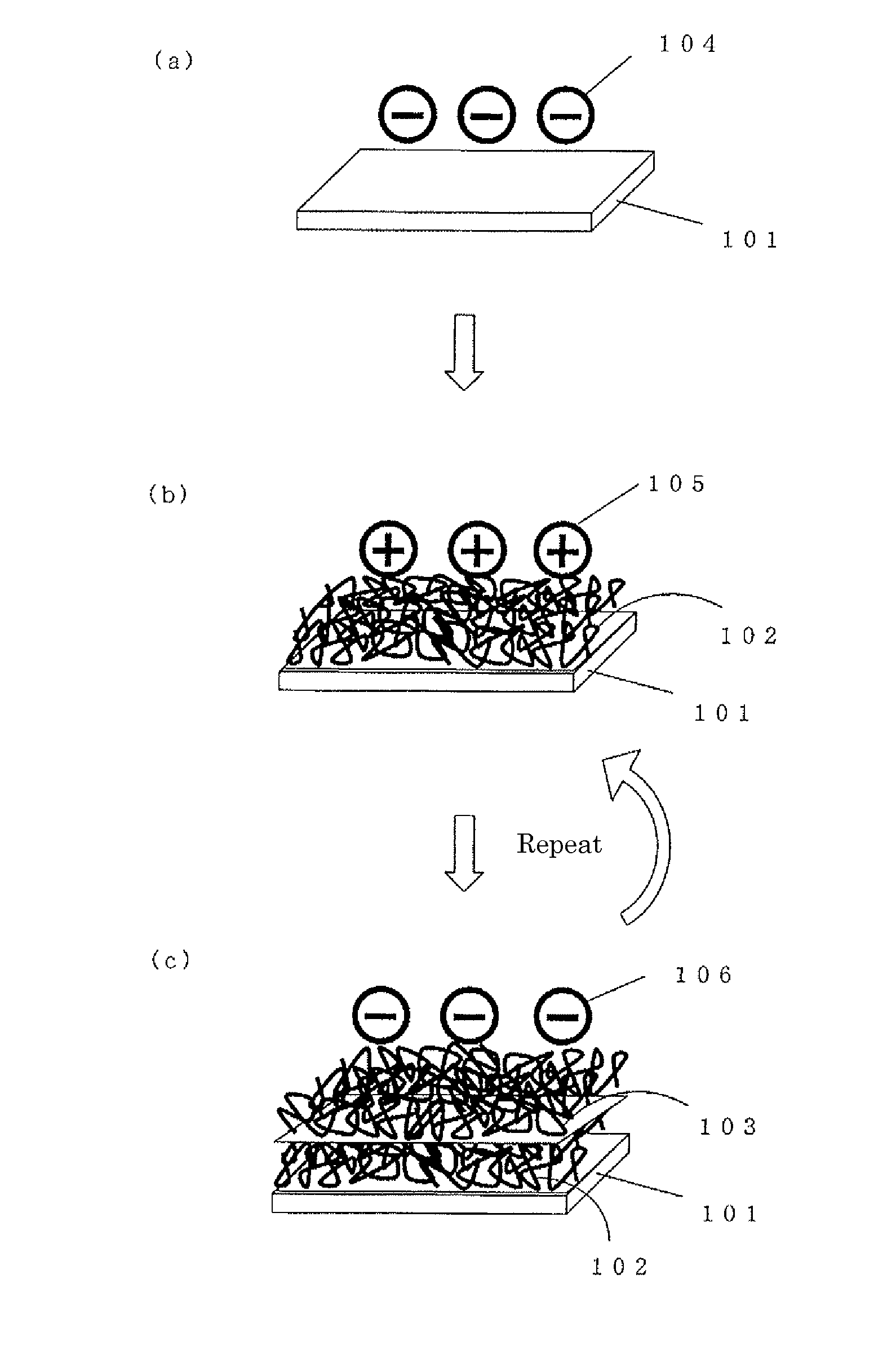
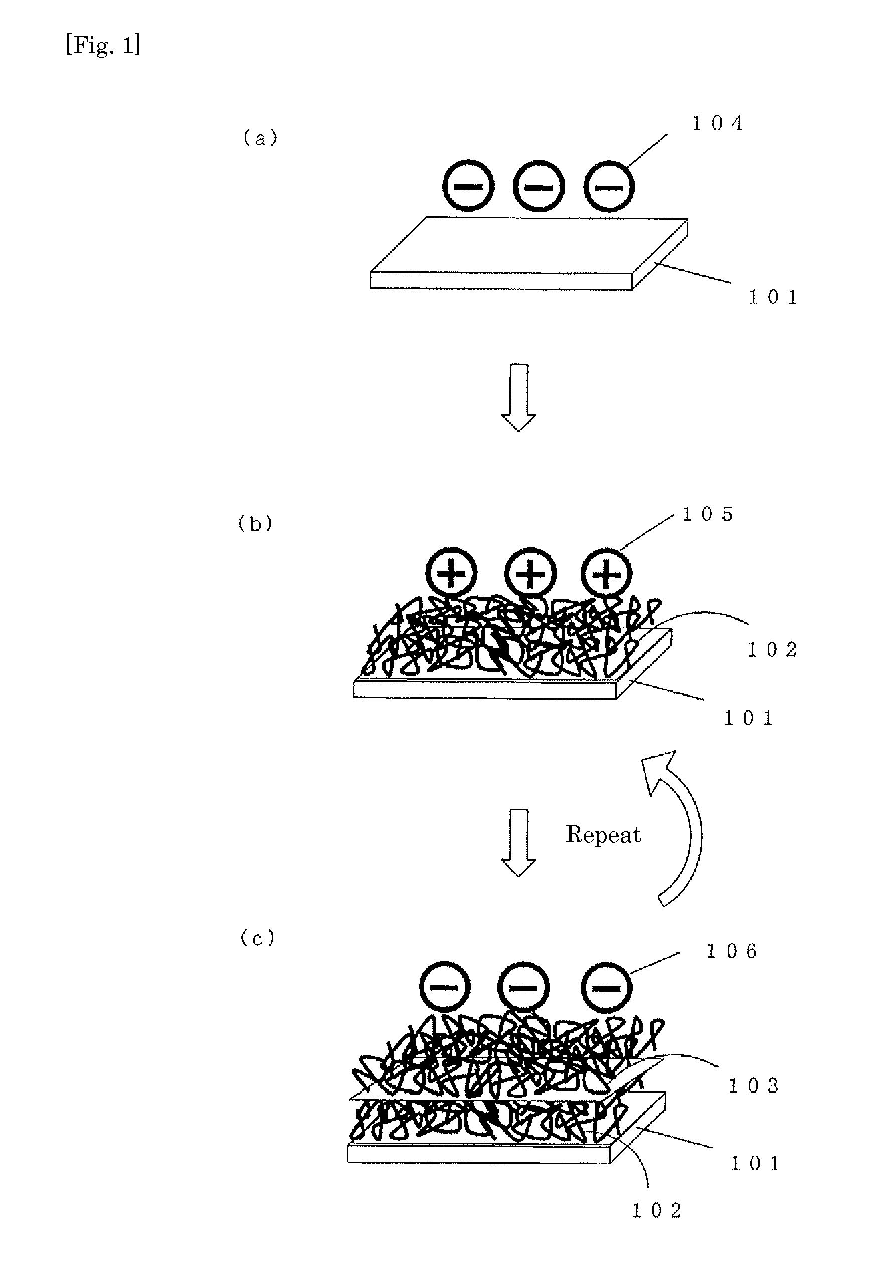
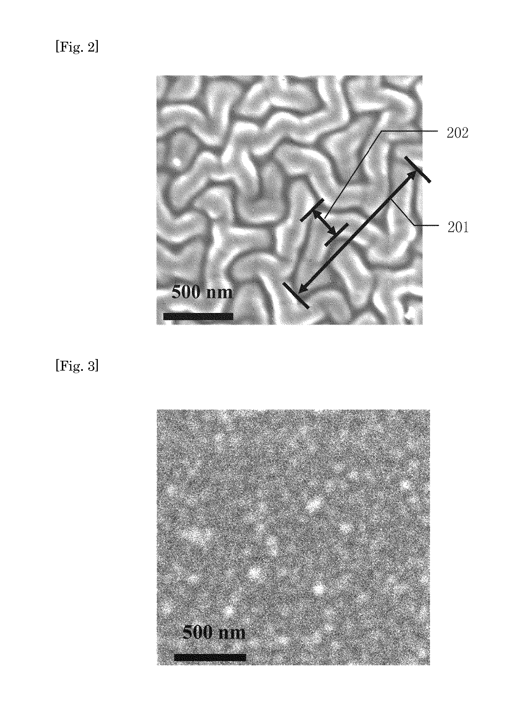
[0050]A glass plate previously charged negatively was immersed in 100 mM polydiallyldimethylammonium chloride (PDDA) solution for 15 minutes, forming a polycation layer; it was then immersed in purified water for cleaning thrice for 2 minutes, 1 minute and 1 minute; it was then immersed in 1;1 mixture solution of polyvinylalcohol (PVA: molecular weight; 1500, 1 wt %) and polyacrylic acid (PAA molecular weight; 90000, 20 mM), forming a polyanion layer; and it was then immersed in purified water for cleaning thrice for 2 minutes, 1 minute and 1 minute. The operation above was repeated 20 times (lamination number: 20), forming a PVA / PAA surface having a negatively charged outermost layer on the glass plate. The SEM image of the surface is shown in FIG. 2. As shown in FIG. 2, the surface had a three-dimensional texture structure having surface irregularity. Subsequently, the length 201 of the constituent elements in the three-dimensional texture structure, as determined under SEM, was a...

example 2

[0055]A PVA / PAA surface having a three-dimensional texture structure having a negatively charged outermost layer and an irregular surface similar to that in Example 1 was formed on the filter region of a catheter-shaped medical device previously negatively charged that is to be installed in blood vessel for capturing embolus-causing substances (304 stainless steel, diameter 20 μm, opening: 100 μm) at a lamination number of 20, by an operation similar to that in Example 1. The length of the constituent elements in the three-dimensional texture structure, as determined then under SEM, was averagely 3 μm or less; the width was averagely 500 nm or less; the surface irregularity in the depth direction was 70 nm; and the thickness of the alternately laminated polymer layer was 1000 nm.

example 3

[0056]A PVA / PAA surface having a three-dimensional texture structure having a negatively charged outermost layer and an irregular surface, similar to that in Example 1 was formed on the filter region of a catheter-shaped medical device previously negatively charged that is to be installed in blood vessel for capturing embolus-causing substances (304 stainless steel, diameter 20 μm, opening: 100 μm) at a lamination number of 5 by an operation similar to that in Example 1. The length of the constituent elements in the three-dimensional texture structure, as determined then under SEM, was averagely 3 μm or less; the width was averagely 500 nm or less; the surface irregularity in the depth direction was 15 nm; and the thickness of the alternately laminated polymer layer was 200 nm.


PUM

PropertyMeasurementUnit
Thicknessaaaaaaaaaa
Thicknessaaaaaaaaaa
Depthaaaaaaaaaa

Abstract

Provided is a surface showing excellent antithrombotic properties. Also provided is a medical device having the same. An antithrombotic surface comprising polymer layers which are in different charged states and alternately layered, characterized by having three-dimensional peaks and valleys formed thereon. The antithrombotic surface as described above which is further characterized in that the peaks and valleys are 15 nm or more but not more than 200 nm in height and depth respectively. A medical device characterized by being provided with the antithrombotic surface as described above. Thus, a thin and highly antithrombotic surface or medical device can be obtained by a relatively convenient method.

Description

TECHNICAL FIELD[0001]The present invention relates to a laminated film having a surface superior in biocompatibility, particularly in antithrombogenicity (blood clotting resistance) and additionally to a medical device having a region where the surface thereof is coated with the laminated film.BACKGROUND ART[0002]A great number of medical devices have been development recently along with progress in medicine, and medical devices which are brought into contact with blood, such as catheter, artificial heart-lung machine, artificial kidney, artificial cardiac valve, and hemocathartic system, among them, are made of polymer materials and metal materials. These medical devices, when brought into contact with blood, may cause thrombosis by coagulation of the blood on the surface, leading to deterioration in performance during use of the medical devices and further causing clinical problems.[0003]Various antithrombogenic surfaces have been developed to solve the problems above. Examples th...

Claims


Application Information

Patent Timeline
IPC IPC(8): A61L33/00B32B3/00B32B33/00B32B37/24
CPCA61L27/34A61L29/085Y10T428/24355A61L33/062A61L31/10
Inventor SHIRATORI, SEIMEIKUWAKI, ORIHAKIM, JIN-HOFUKAYA, KOHEIMIHAYASHI, TSUYOSHI
Owner KANEKA CORP
Why Eureka
Try Eureka