Logic circuit and semiconductor device
a logic circuit and semiconductor technology, applied in the field of logic circuits, can solve the problems of low on-off ratio of thin film transistors, unstable operation of circuits including thin film transistors with low on-off ratios, and reduce hydrogen concentration, reduce the current of off-state transistors, and suppress the leakage of electric charge stored in capacitors through thin film transistors.
- Summary
- Abstract
- Description
- Claims
- Application Information
AI Technical Summary
Benefits of technology
Problems solved by technology
Method used
Image
Examples
embodiment 1
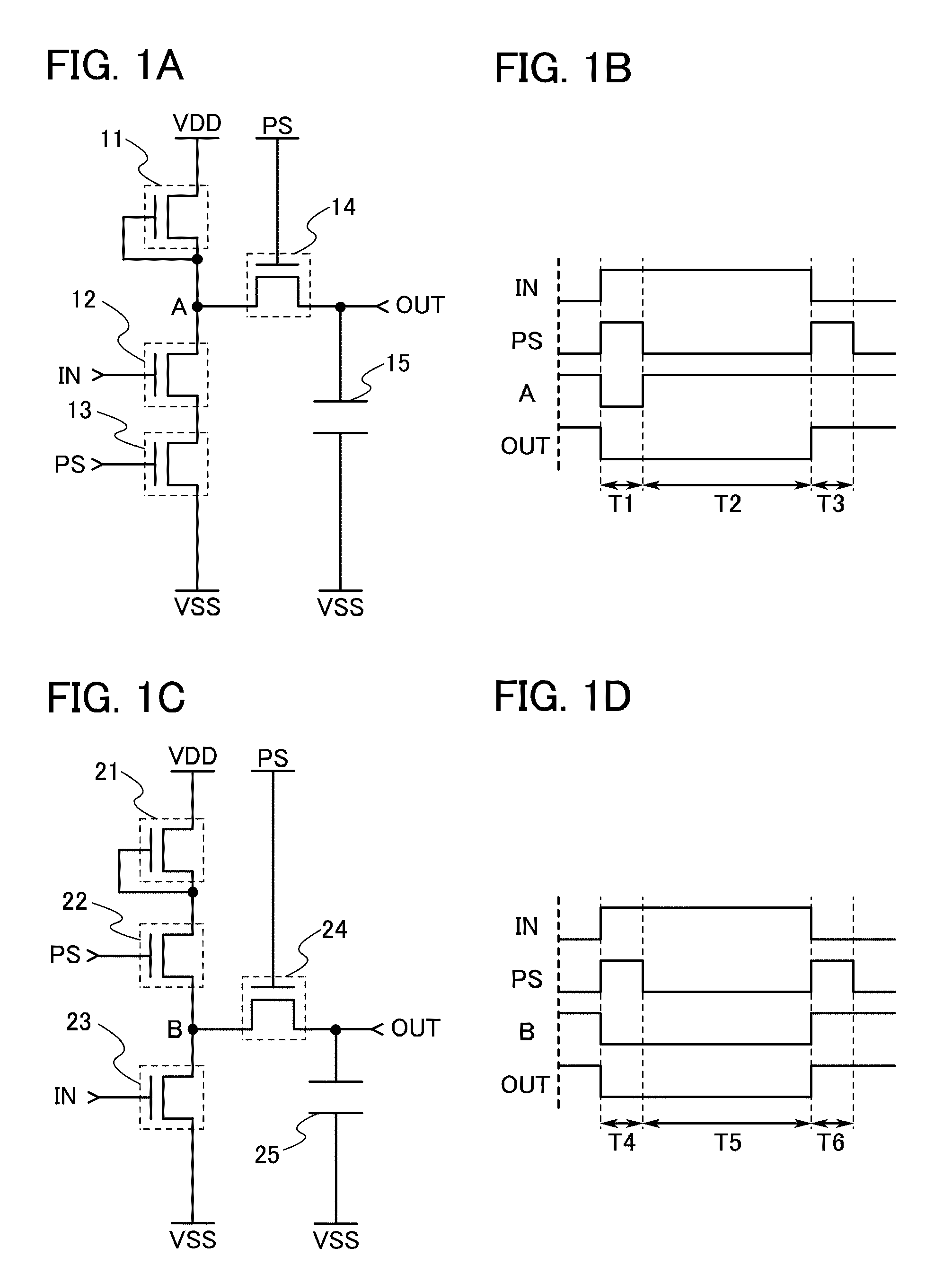
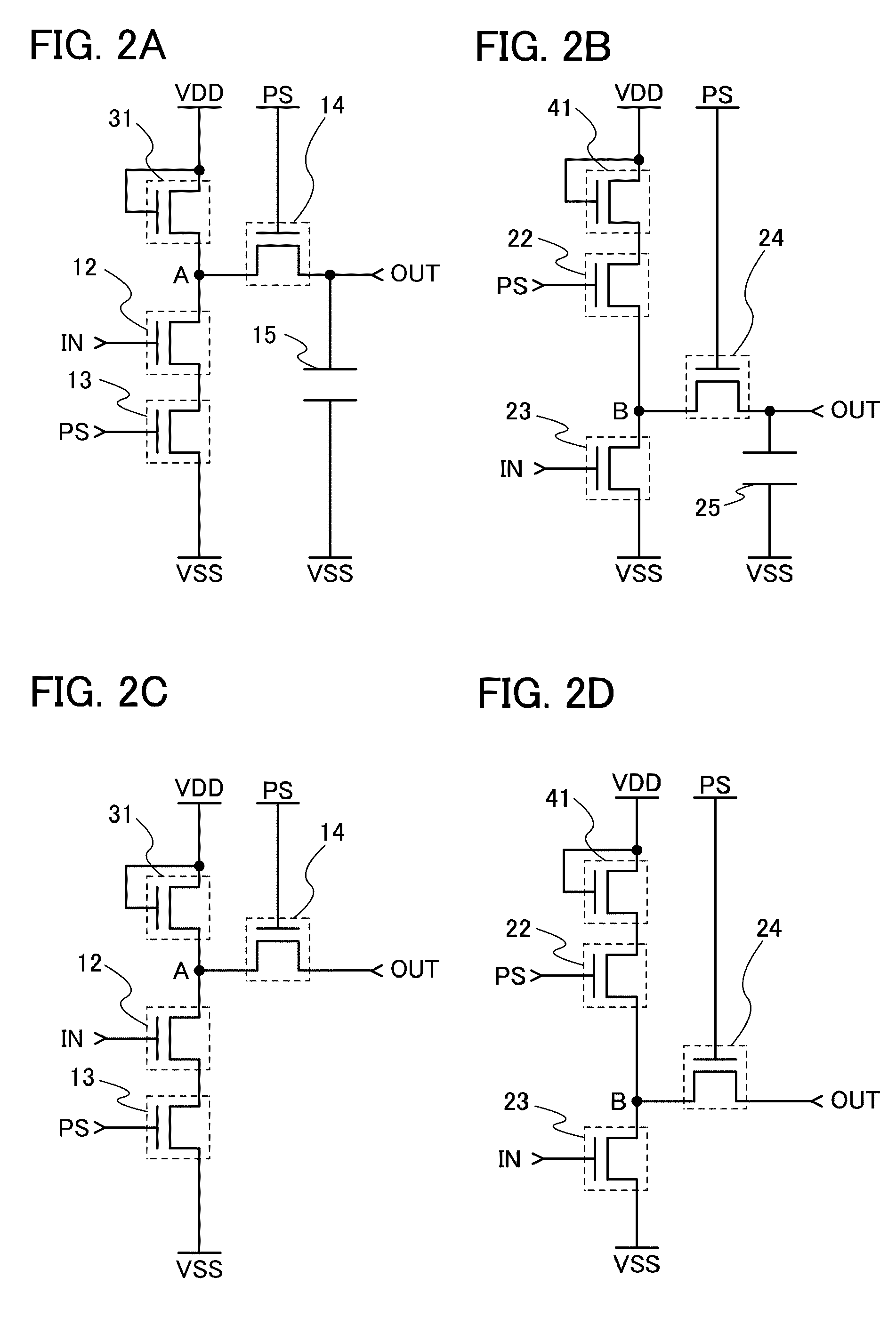
[0056]In this embodiment, examples of logic circuits are described. Specifically, examples of inverters each including a thin film transistor having a channel formation region which is formed using an oxide semiconductor are described with reference to FIGS. 1A to 1D and FIGS. 2A to 2D.
[0057]FIG. 1A is a circuit diagram illustrating an example of an inverter of this embodiment. The inverter illustrated in FIG. 1A includes thin film transistors 11 to 14 and a capacitor 15. Here, the thin film transistor 11 is a depletion type transistor and the thin film transistors 12 to 14 are enhancement type transistors. Note that in this specification, an n-channel transistor whose threshold voltage is positive is referred to as an enhancement type transistor, and an n-channel transistor whose threshold voltage is negative is referred to as a depletion type transistor.
[0058]A first terminal of the thin film transistor 11 is electrically connected to a wiring for supplying a high power supply pot...
embodiment 2
[0090]In this embodiment, examples of logic circuits are described. Specifically, examples of shift registers each including the inverter in Embodiment 1 are described with reference to FIGS. 3A and 3B and FIGS. 4A and 4B.
[0091]A shift register of this embodiment includes a plurality of pulse output circuits; a wiring for supplying a first clock signal (CK1), which is electrically connected to odd-numbered pulse output circuits of the plurality of pulse output circuits (hereinafter, such a wiring is also referred to as a first clock signal line); and a wiring for supplying a second clock signal (CK2), which is electrically connected to even-numbered pulse output circuits of the plurality of pulse output circuits (hereinafter, such a wiring is also referred to as a second clock signal line). Further, an input terminal of each pulse output circuit is electrically connected to a wiring for supplying a start pulse signal (SP) (hereinafter, such a wiring is also referred to as a start pu...
embodiment 3
[0146]In this embodiment, an example of thin film transistors included in the logic circuit in Embodiment 1 or Embodiment 2 is described.
[0147]One embodiment of a thin film transistor and a manufacturing method of the thin film transistor of this embodiment is described with reference to FIGS. 5A and 5B and FIGS. 6A to 6E.
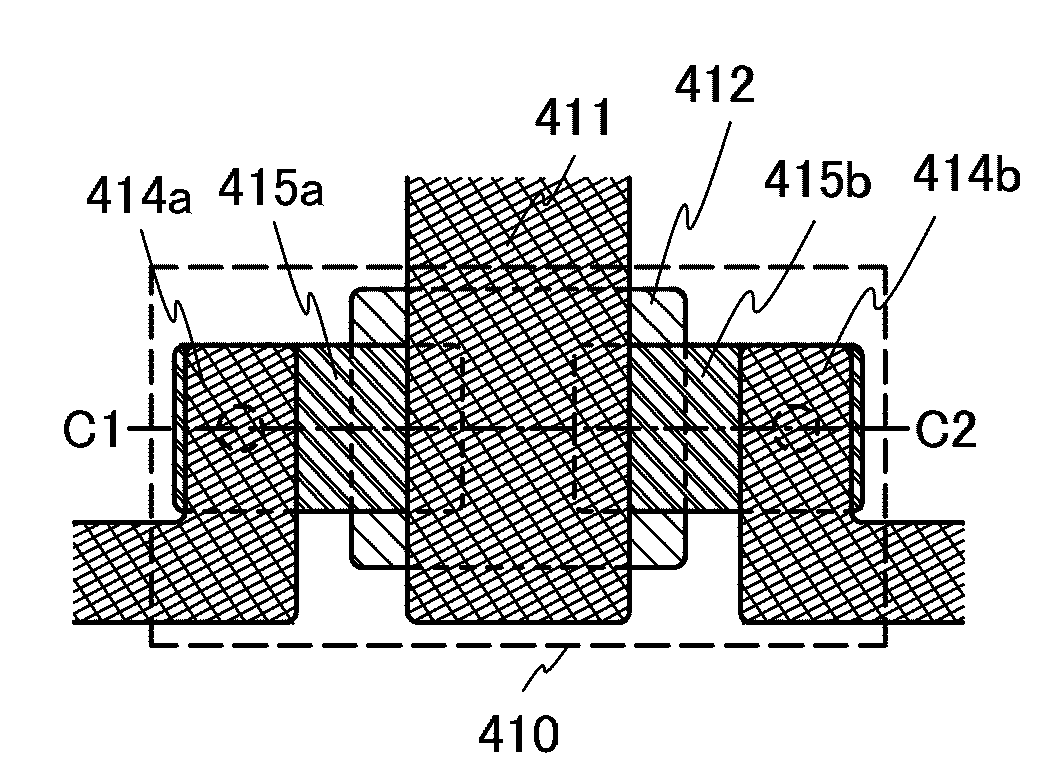
[0148]FIGS. 5A and 5B illustrate an example of a planar structure and a cross-sectional structure of a thin film transistor. A thin film transistor 410 illustrated in FIGS. 5A and 5B is one of top gate thin film transistors.
[0149]FIG. 5A is a plan view of the thin film transistor 410 having a top-gate structure and FIG. 5B is a cross-sectional view taken along a line C1-C2 in FIG. 5A.
[0150]The thin film transistor 410 includes, over a substrate 400 having an insulating surface, an insulating layer 407, an oxide semiconductor layer 412, a source or drain electrode layer 415a, a source or drain electrode layer 415b, a gate insulating layer 402, and a gate electrode l...
PUM
 Abstract
Description
Claims
Application Information
 - R&D
- Intellectual Property
- Life Sciences
- Materials
- Tech Scout
- Unparalleled Data Quality
- Higher Quality Content
- 60% Fewer Hallucinations
Browse by: Latest US Patents, China's latest patents, Technical Efficacy Thesaurus, Application Domain, Technology Topic, Popular Technical Reports.
© 2025 PatSnap. All rights reserved.Legal|Privacy policy|Modern Slavery Act Transparency Statement|Sitemap|About US| Contact US: help@patsnap.com


