Lithium microbattery provided with an electronically conductive packaging layer

Active Publication Date: 2011-04-28
COMMISSARIAT A LENERGIE ATOMIQUE ET AUX ENERGIES ALTERNATIVES
View PDF6 Cites 13 Cited by
  • Summary
  • Abstract
  • Description
  • Claims
  • Application Information

AI Technical Summary

Benefits of technology

In particular, the object of the invention is to propose a microbattery the production whereof is simplified, with inex

Problems solved by technology

Without the presence of a packaging thin layer, expansion and/or contraction of the microbattery components could in fa

Method used


Image

  • Lithium microbattery provided with an electronically conductive packaging layer
  • Lithium microbattery provided with an electronically conductive packaging layer
  • Lithium microbattery provided with an electronically conductive packaging layer

Examples


Embodiment Construction

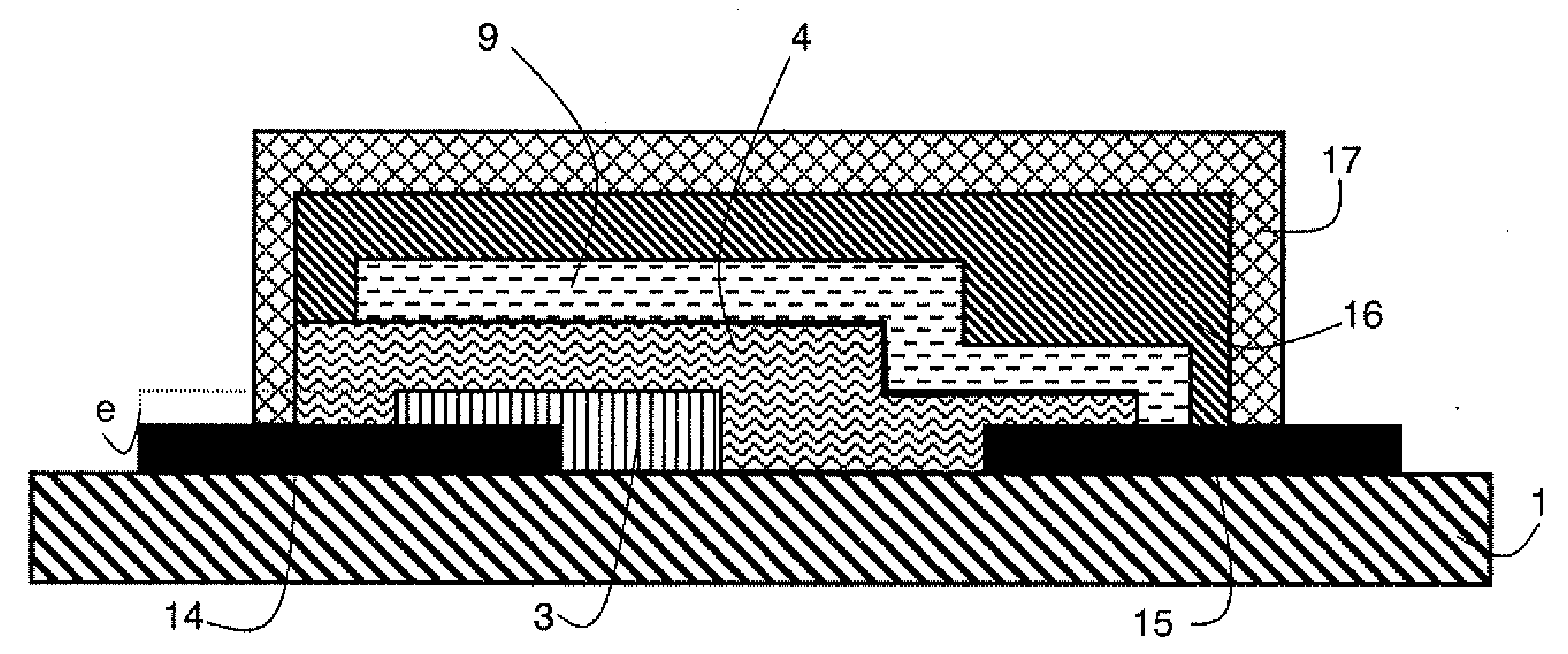
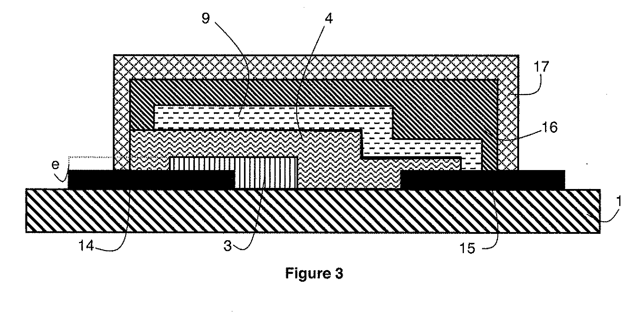
According to an embodiment represented in FIG. 3, a lithium microbattery comprises a substrate 1 one surface whereof is partially covered by a multi-layer stack forming the active parts of the microbattery, and by at least one thin layer protecting the active parts of the microbattery.

For example, substrate 1 consists of silicon. Substrate 1 can also in certain cases contain an integrated circuit (not shown in FIG. 3) or it can in an alternative embodiment be replaced by a metallic support.

In FIG. 3, the multilayer stack forming the active parts of the microbattery successively comprises:two metallic thin layers 14 and 15 arranged directly on the surface of substrate 1,a thin layer forming the positive electrode or cathode 3,a solid electrolyte 4,and a thin layer forming the negative electrode or anode 9.

The two metallic thin layers 14 and 15 are arranged directly on the surface of substrate 1 and they are separated from one another so as not to be in contact with one another. They ...


PUM


Abstract

A lithium microbattery comprises a packaging thin layer formed by a matrix of polymer material in which metallic particles are dispersed. The packaging thin layer constitutes at least a part of the anodic current collector of the lithium microbattery. The polymer material is advantageously obtained from at least a photopolymerizable precursor material chosen from bisphenol A diglycidylether, bisphenol F butanediol diglycidil ether, 7-oxabicylco[4.1.0]heptane-3-carboxylate of 7-oxabicylco[4.1.0]hept-3-ylmethyl and a mixture of bisphenol A and epichloridine. It can also be a copolymer obtained from a homogenous mixture of at least two photopolymerizable precursor materials, respectively acrylate-base, such as diacrylate 1,6-hexanediol and methacrylate, and epoxide-base, for example chosen from bisphenol A diglycidylether, 7-oxabicylco[4.1.0]heptane-3-carboxylate of 7-oxabicylco[4.1.0]hept-3-ylmethyl and a mixture of bisphenol A and epichloridine.

Description

BACKGROUND OF THE INVENTIONThe invention relates to a lithium microbattery comprising a packaging thin layer made from polymer material and an anodic current collector.STATE OF THE ARTA lithium microbattery generally comprises a stack of solid thin layers successively deposited on a substrate by conventional deposition techniques used in the microelectronics field. A lithium microbattery stack comprises in particular:metallic current collectors, for example made from titanium, platinum or tungsten,a positive electrode (or cathode) which is both an electron and ion conductor, for example made from titanium oxysulfide (TiOS), TiS2 or V2O5,a solid electrolyte, for example UPON,and a negative electrode (or anode).Depending on the nature of the anode, lithium microbatteries are in general classified according to two types of batteries:batteries called “Li-metal” for negative electrodes composed of metallic lithium,and batteries called “Li-ion” for negative electrodes formed by lithium in...

Claims


Application Information

Patent Timeline
IPC IPC(8): H01M2/08H01M50/122
CPCH01M2/0275H01M4/134H01M4/668H01M6/40Y02E60/122H01M10/052H01M10/0525H01M10/0585H01M10/0436Y02P70/50Y02E60/10H01M50/122
Inventor BEDJAOUI, MESSAOUDMARTIN, STEVESALOT, RAPHAEL
Owner COMMISSARIAT A LENERGIE ATOMIQUE ET AUX ENERGIES ALTERNATIVES
Why Eureka
Try Eureka