Systems and processes for operating fuel cell systems

a fuel cell and process technology, applied in the direction of fuel cells, chemistry apparatus and processes, electrochemical generators, etc., can solve the problems of less hydrogen produced by the water-gas shift reaction, disfavorable water-based carbon dioxide and hydrogen production, and fuel gases containing non-hydrogen compounds such as carbon monoxide, less efficient for producing electrical power in molten carbonate fuel cells

Inactive Publication Date: 2011-05-12
SHELL OIL CO
View PDF34 Cites 37 Cited by
  • Summary
  • Abstract
  • Description
  • Claims
  • Application Information

AI Technical Summary

Benefits of technology

[0037]a molten carbonate fuel cell configured to receive a hydrogen-containing stream comprising molecular hydrogen at a flow rate such that hydrogen utilization in an anode of the molten carbonate fuel cell is less than 50%;
[0038]one or more reformers operatively coupled to the molten carbonate fuel cell, at least one reformer being configured to receive anode exhaust from the molten carbonate fuel cell and hydrocarbons, and being configured to allow the anode exhaust to sufficiently mix with hydrocarbons to at least partially reform some of the hydrocarbons to produce a reformed product stream, wherein the reformed product stream comprises molecular hydrogen and at least one carbon oxide; and
[0039]a high temperature hydrogen-separation device that is part of, or coupled to, at least one of the reformers and operatively coupled to the molten carbonate fuel cell, wherein the high temperature hydrogen-separation device comprises one or more high temperature hydrogen-separating membranes and is configured to receive a reformed product stream and to provide a stream comprising at least a portion of the molecular hydrogen to the molten carbonate fuel cell.

Problems solved by technology

In a conventionally operated steam reformer used to supply fuel gas to a molten carbonate fuel cell, however, little hydrogen is produced by the water-gas shift reaction since the steam reformer is operated at a temperature that energetically favors the production of carbon monoxide and hydrogen by the steam reforming reaction.
Operating at such a temperature disfavors the production of carbon dioxide and hydrogen by the water-gas shift reaction.
Fuel gases containing non-hydrogen compounds such as carbon monoxide, however, are less efficient for producing electrical power in a molten carbonate fuel cell than more pure hydrogen fuel gas streams.
Therefore, fuel gas streams containing significant amounts of non-hydrogen compounds are not as efficient in producing electrical power in a molten carbonate fuel cell as fuel gases containing mostly hydrogen.
Certain measures have been taken to recapture the energy of the hydrogen exiting the fuel cell, however, these are significantly less energy efficient than if the hydrogen were electrochemically reacted in the fuel cell.
Doing so, however, is significantly less efficient than capturing the electrochemical potential of the hydrogen in the fuel cell since much of the thermal energy is lost rather than converted by the expander to electrical energy.
Almost 50% of the thermal energy, however, is lost in such heat exchange applications after combustion.
Hydrogen is a very expensive gas to use to fire a burner utilized in inefficient energy recovery systems and, therefore, conventionally, the amount of hydrogen used in the molten carbonate fuel cell is adjusted to utilize most of the hydrogen provided to the fuel cell to produce electrical power and minimize the amount of hydrogen exiting the fuel cell in the fuel cell exhaust.
These methods for providing the heat necessary to drive steam reforming reactions and / or water-gas shift reactions are relatively inefficient energetically since a significant amount of thermal energy provided by combustion is not captured and is lost.
The stream may be cooled, for example, through a heat exchanger, however, thermal energy may be lost in the cooling process.
While the prior art is effective in providing hydrogen, oxygen, and carbon dioxide to the fuel cell at different concentrations, the process is relatively inefficient in producing the hydrogen, carbon dioxide, and oxygen streams.
The process is also relatively thermally inefficient in production of the gases and thermal processes since the anode gas is cooled to remove the water prior to entering the pressure swing adsorption units.
In addition, the reformers also do not convert a liquid hydrocarbon feedstock to a lower molecular weight feed for the steam reformer, and insufficient heat is likely provided from the fuel cell to do so.

Method used


Image

  • Systems and processes for operating fuel cell systems
  • Systems and processes for operating fuel cell systems
  • Systems and processes for operating fuel cell systems

Examples


examples

[0175]Non-restrivtive examples are set forth below.

[0176]A UniSim® simulation program (Honeywell) in combination with calculations for cell potential was used to construct a detailed process simulation for the molten carbonate fuel cell systems of the present invention. The UniSim program was used to obtain material balance and energy balance data. The detailed process simulation was repeatedly solved for the different values of hydrogen utilization, and other relevant system parameters. The detailed process simulation output included detailed composition data for all process streams entering and exiting the molten carbonate fuel cell. For high temperature fuel cells, activation losses are small and the cell potential may be obtained over the practical range of current densities by considering only ohmic and electrode losses. As such, the cell potential (V) of a molten carbonate fuel cell is the difference between the open circuit voltage (E) and the losses (iR) as shown in Equation...

examples 1

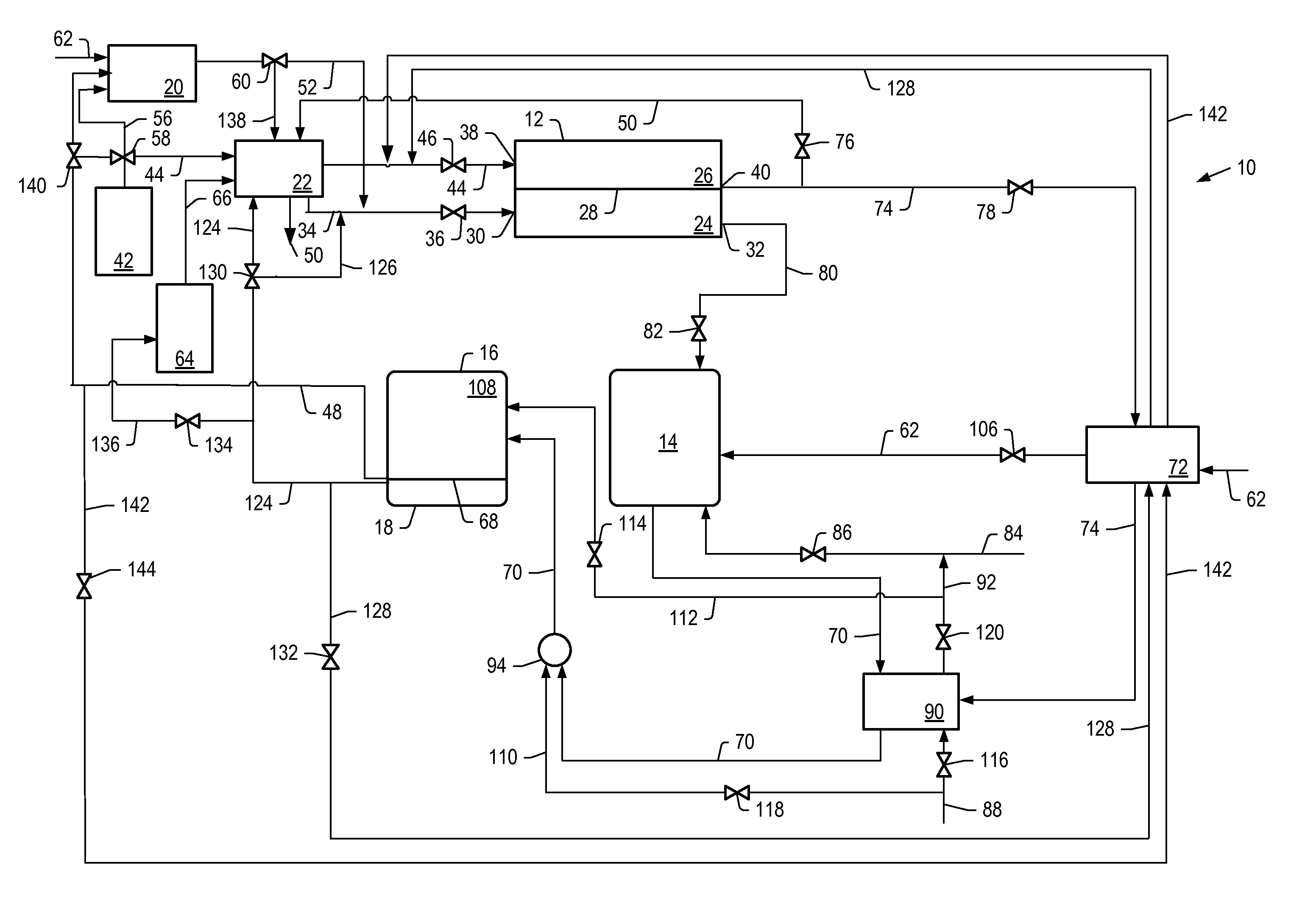
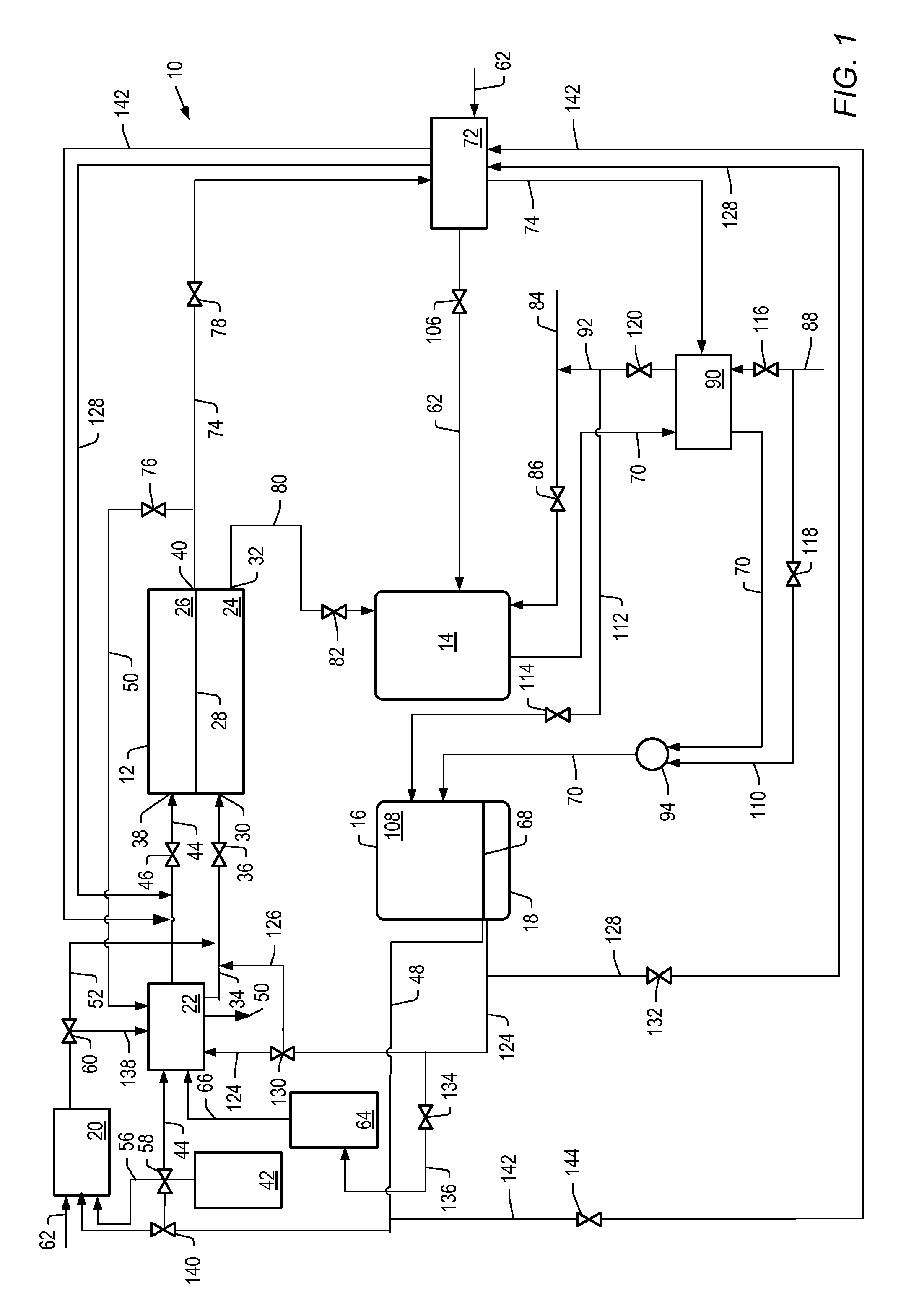
[0177]The detailed process simulations described above was used to simulate cell voltage versus current density and power density formation for molten carbonate fuel cell systems described herein where the first reformer was heated by the anode exhaust, with no other heating. For example, systems depicted by FIG. 1. The heat for the second reformer was heated by exchange with the hot effluent from the catalytic partial oxidation reformer. The output temperature of the effluent from the catalytic partial oxidation reformer was increased by using the cathode exhaust to preheat the catalytic oxidation reformer air feed.
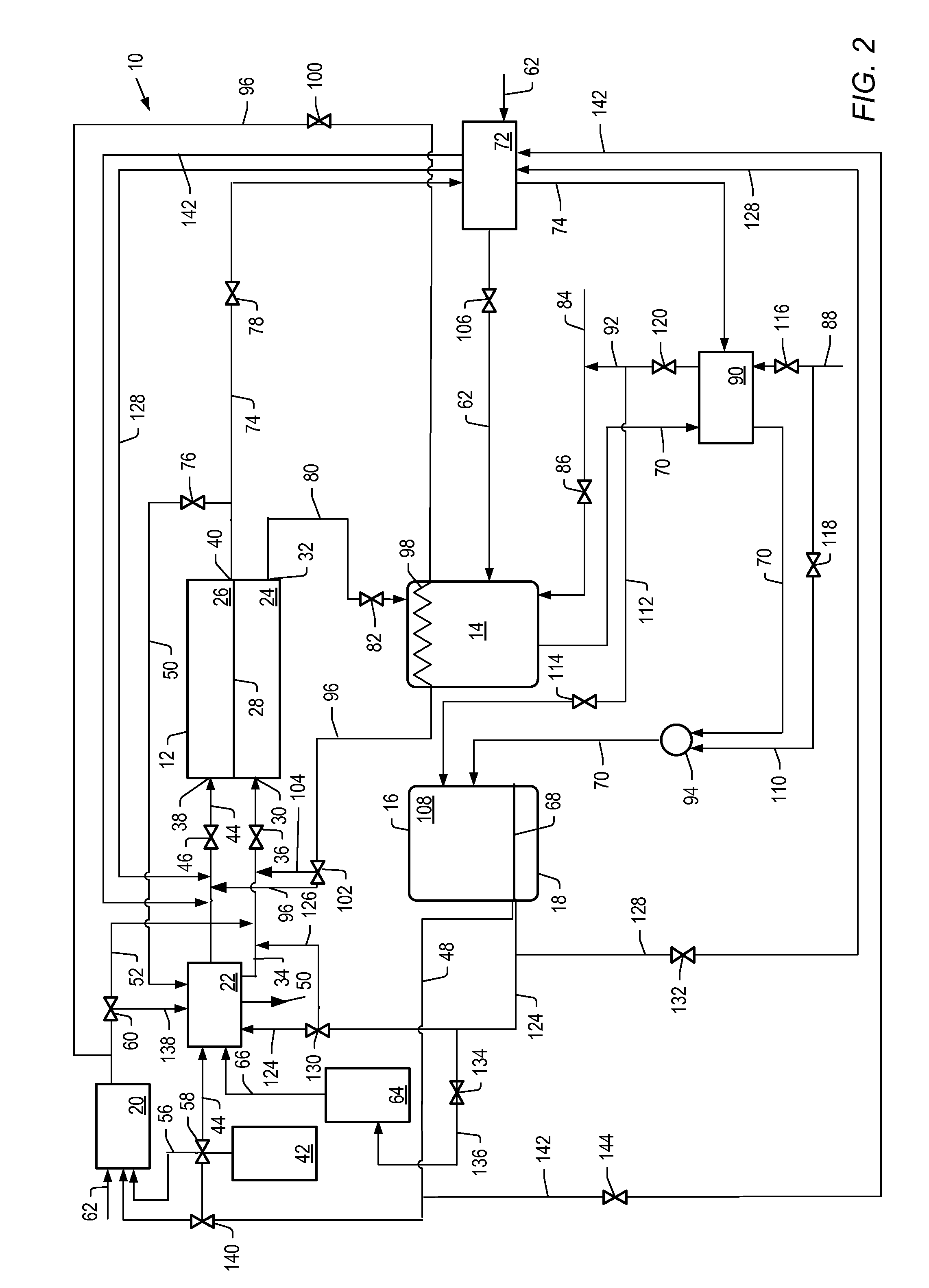
example 2

[0178]The simulation described above was used to simulate cell voltage versus current density and power density formation for molten carbonate fuel cell systems described herein where the first reformer is heated by anode exhaust and heat from a catalytic partial oxidation reformer. For example, systems depicted in FIG. 2.

[0179]For Examples 1 and 2, the molten carbonate fuel cell was operated at a pressure of 1 bara (about 0.1 MPa or about 1 atm) and a temperature of 650° C. The flow of feed to the cathode of the molten carbonate fuel cell was counter current to the flow of feed to the anode. Air was used as the source of oxygen. Values for air were used to produce a molar ratio of carbon dioxide to molecular oxygen of 2 at various hydrogen utilizations. The percent hydrogen utilization for the molten carbonate fuel cell, operating conditions of the first and second reformer, steam to carbon ratios, and percent conversion of benzene to hydrogen for Example 1 and 2 simulations are li...


PUM

PropertyMeasurementUnit
temperatureaaaaaaaaaa
carbon numberaaaaaaaaaa
molar ratioaaaaaaaaaa

Abstract

Processes and systems for operating molten carbonate fuel cell systems are described herein. A process for operating a molten carbonate fuel cell system includes providing a hydrogen-containing stream comprising molecular hydrogen to an anode portion of a molten carbonate fuel cell; controlling a flow rate of the hydrogen-containing stream to the anode such that molecular hydrogen utilization in the anode is less than 50%; mixing anode exhaust comprising molecular hydrogen from the molten carbonate fuel cell with a hydrocarbon stream comprising hydrocarbons, contacting at least a portion of the mixture of anode exhaust and the hydrocarbon stream with a catalyst to produce a steam reforming feed; separating at least a portion of molecular hydrogen from the steam reforming feed; and providing at least a portion of the separated molecular hydrogen to the molten carbonate fuel cell anode.

Description

[0001]This is a continuation in part of U.S. application Ser. No. 12 / 797,543, filed Jun. 9, 2010, which claims the benefit of U.S. Provisional Application No. 61 / 187,539, filed on Jun. 16, 2009, which applications are hereby incorporated herein by reference.FIELD OF THE INVENTION[0002]The present invention relates to fuel cell systems and to processes of operating fuel cells. In particular, the present invention relates to systems and processes of operating a molten carbonate fuel cell system.BACKGROUND OF THE INVENTION[0003]Molten carbonate fuel cells convert chemical energy into electrical energy. Molten carbonate fuel cells are useful in that they deliver high quality reliable electrical power, are clean operating, and are relatively compact power generators. These features make the use of molten carbonate fuel cells attractive as power sources in urban areas, shipping vessels, or remote areas with limited access to power supplies.[0004]Molten carbonate fuel cells are formed of a...

Claims


Application Information

Patent Timeline
Patent Type & Authority Applications(United States)
IPC IPC(8): H01M8/06
CPCC01B3/38H01M2008/147C01B3/386C01B3/48C01B3/501C01B2203/0233C01B2203/0261C01B2203/0283C01B2203/041C01B2203/047C01B2203/0475C01B2203/066C01B2203/0827C01B2203/0833C01B2203/0883C01B2203/1235C01B2203/141C01B2203/142C01B2203/148C01B2203/169H01M8/04022H01M8/04097H01M8/04753H01M8/0618H01M8/145Y02E60/526C01B3/382Y02E60/50
Inventor CUI, JINGYUENGWALL, ERIK EDWINJOHNSTON, JOHN WILLIAMJOSHI, MAHENDRA LADHARAMWELLINGTON, SCOTT LEE
Owner SHELL OIL CO
Why Eureka
Try Eureka