Systems and processes of operating fuel cell systems

a fuel cell and process technology, applied in the direction of fuel cells, fused electrolyte fuel cells, electrical equipment, etc., can solve the problems of less hydrogen produced by the water-gas shift reaction, disfavorable the production of carbon dioxide and hydrogen by the water, and fuel gases containing non-hydrogen compounds such as carbon monoxide, less efficient for producing electrical power in molten carbonate fuel cells than more pure hydrogen fuel gas streams

Inactive Publication Date: 2011-05-12
SHELL OIL CO
View PDF11 Cites 140 Cited by
  • Summary
  • Abstract
  • Description
  • Claims
  • Application Information

AI Technical Summary

Benefits of technology

[0036]one or more reformers operatively coupled to the molten carbonate fuel cell, at least one reformer being configured to receive anode exhaust from the molten carbonate fuel cell and to receive a hydrocarbon stream, at least a majority of which is comprised of hydrocarbons that are liquid at 20° C. and atmospheric pressure, and to allow the anode exhaust to sufficiently mix with a portion of the hydrocarbon stream to at least partially reform some of the hydrocarbons to

Problems solved by technology

In a conventionally operated steam reformer used to supply fuel gas to a molten carbonate fuel cell, however, little hydrogen is produced by the water-gas shift reaction since the steam reformer is operated at a temperature that energetically favors the production of carbon monoxide and hydrogen by the steam reforming reaction.
Operating at such a temperature disfavors the production of carbon dioxide and hydrogen by the water-gas shift reaction.
Fuel gases containing non-hydrogen compounds such as carbon monoxide, however, are less efficient for producing electrical power in a molten carbonate fuel cell than more pure hydrogen fuel gas streams.
Therefore, fuel gas streams containing significant amounts of non-hydrogen compounds are not as efficient in producing electrical power in a molten carbonate fuel cell as fuel gases containing mostly hydrogen.
Certain measures have been taken to recapture the energy of the hydrogen exiting the fuel cell, however, these are significantly less energy efficient than if the hydrogen were electrochemically reacted in the fuel cell.
Doing so, however, is significantly less efficient than capturing the electrochemical potential of the hydrogen in the fuel cell since much of the thermal energy is lost rather than converted by the expander to electrical

Method used


Image

  • Systems and processes of operating fuel cell systems
  • Systems and processes of operating fuel cell systems
  • Systems and processes of operating fuel cell systems

Examples


example 1

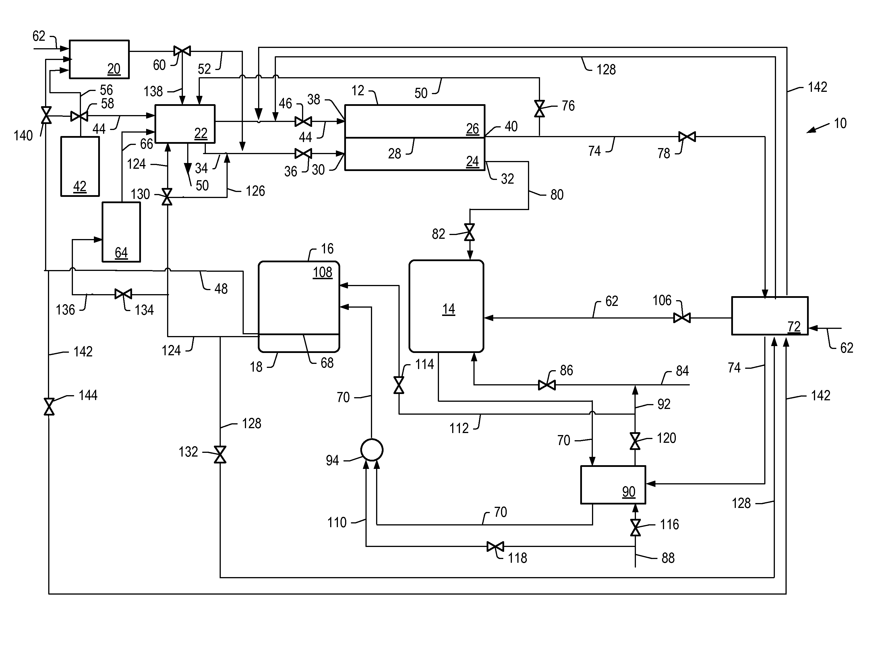
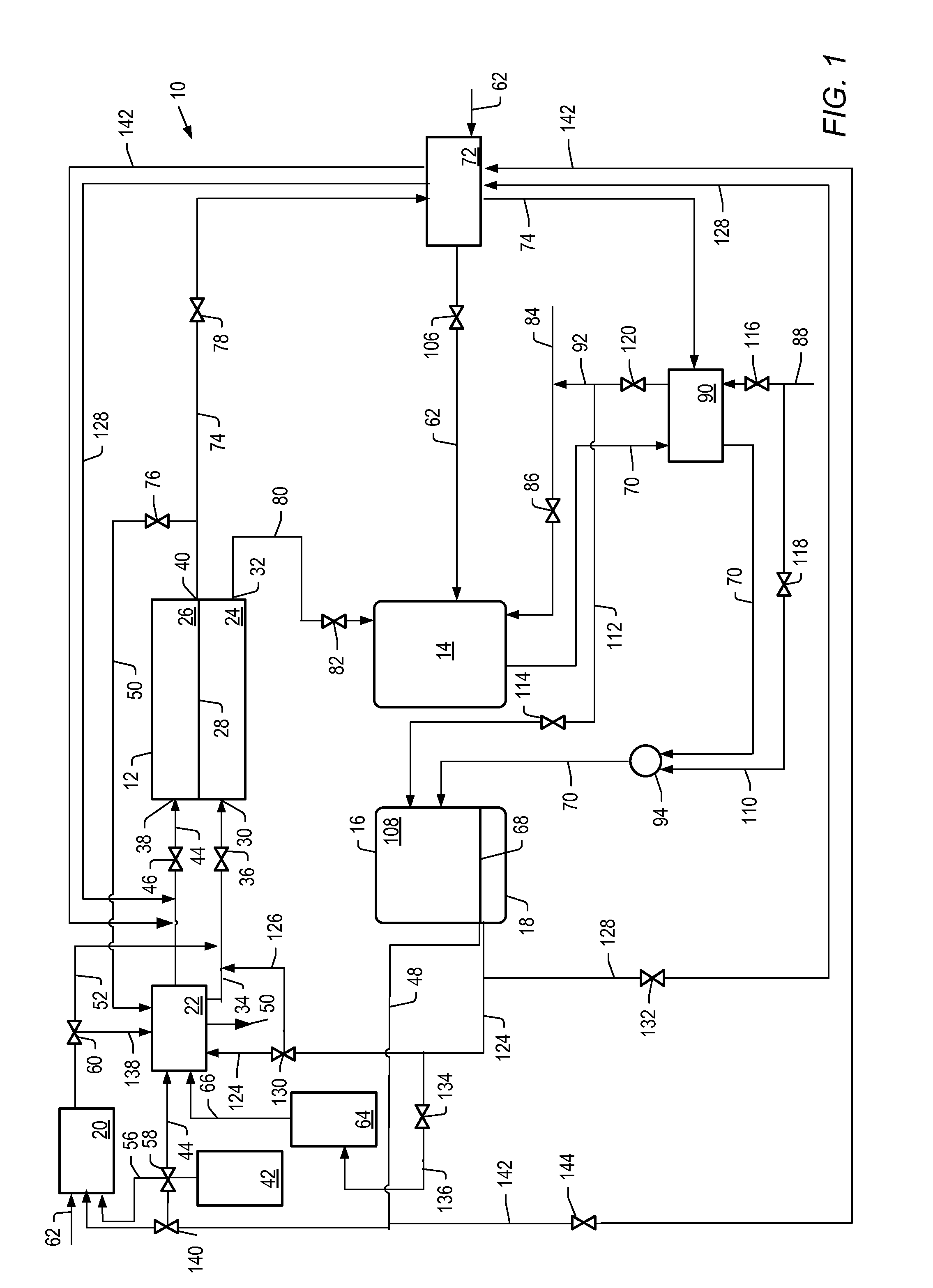
[0167]The detailed process simulation described above was used to simulate cell voltage versus current density and power density formation for the molten carbonate fuel cell systems described herein where the first reformer was heated by the anode exhaust, with no other heating. For example, systems depicted by FIG. 1. The heat for the second reformer was heated by exchange with the hot effluent from the catalytic partial oxidation reformer. The output temperature of the effluent from the catalytic partial oxidation reformer was increased by using the cathode exhaust to preheat the catalytic oxidation reformer air feed.

example 2

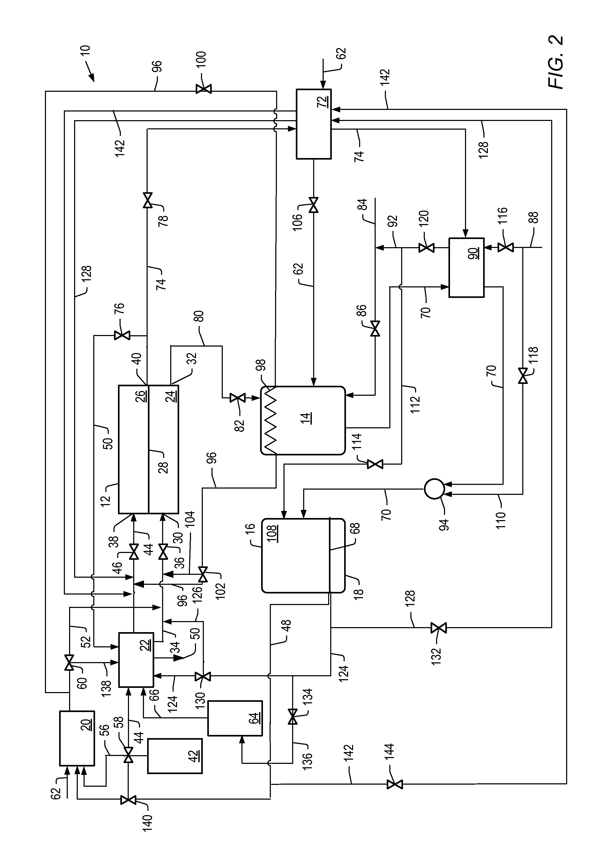
[0168]The simulation described above was used to simulate cell voltage versus current density and power density formation for molten carbonate fuel cell systems described herein where the first reformer is heated by anode exhaust and heat from a catalytic partial oxidation reformer. For example, systems depicted in FIG. 2.

[0169]For Examples 1 and 2, the molten carbonate fuel cell was operated at a pressure of 1 bara (about 0.1 MPa or about 1 atm) and a temperature of 650° C. The flow of feed to the cathode of the molten carbonate fuel cell was counter current to the flow of feed to the anode. Air was used as the source of oxygen. Values for air were used to produce a molar ratio of carbon dioxide to molecular oxygen of 2 at various hydrogen utilizations. The percent hydrogen utilization for the molten carbonate fuel cell, operating conditions of the first and second reformer, steam to carbon ratios, and percent conversion of benzene to hydrogen for Example 1 and 2 simulations are li...

example 3

[0173]The simulations described above were used to determine the current density, cell voltage, and power density for a molten carbonate fuel cell operated at 7 bara (about 0.7 MPa or about 7 atm) for a molten carbonate fuel cell system that includes the first reformer heated by anode exhaust (for example, the system depicted in FIG. 1). The molten carbonate fuel cell was operated at a pressure of 7 bara and a temperature of 650° C. at a hydrogen utilization of 20% or 30%. The first reformer had a steam to carbon ratio of 2.5. The temperature of the first reformer was allowed to be varied. The second reformer, in combination with the high temperature hydrogen-separation device, had a temperature of 500° C. and a pressure of 15 bara. Air was used as the source of oxygen. Values for air were used so that the ratio of carbon dioxide to molecular oxygen in the cathode feed was stoichiometric, thus minimizing cathode side concentration polarization. In all cases, the combined carbon conv...


PUM


Abstract

The present invention is directed to systems and processes for operating molten carbonate fuel cell systems. A process for operating the molten carbonate fuel cell includes providing a hydrogen-containing stream comprising molecular hydrogen to a molten carbonate fuel cell anode; heating a hydrocarbon stream, at least a majority of which is comprised of hydrocarbons that are liquid at 20° C. and atmospheric pressure, with a heat source comprising an anode exhaust from the molten carbonate fuel cell anode; contacting at least a portion of the heated hydrocarbon stream with a catalyst to produce a steam reforming feed comprising gaseous hydrocarbons, hydrogen, and at least one carbon oxide; separating at least a portion of the molecular hydrogen from the steam reforming feed; and providing at least a portion of the separated molecular hydrogen to the molten carbonate fuel cell anode as at least a portion of the stream comprising molecular hydrogen.

Description

[0001]This application claims the benefit of U.S. Provisional Application Ser. No. 61 / 187,550, filed Jun. 16, 2009.FIELD OF THE INVENTION[0002]The present invention relates to fuel cell systems and to processes of operating fuel cells. In particular, the present invention relates to systems and processes of operating molten carbonate fuel cell systems.BACKGROUND OF THE INVENTION[0003]Molten carbonate fuel cells convert chemical energy into electrical energy. Molten carbonate fuel cells are useful in that they deliver high quality reliable electrical power, are clean operating, and are relatively compact power generators. These features make the use of molten carbonate fuel cells attractive as power sources in urban areas, shipping vessels, or remote areas with limited access to power supplies.[0004]Molten carbonate fuel cells are formed of an anode, a cathode, and an electrolytic layer sandwiched between the anode and cathode. The electrolyte includes alkali carbonate salts, alkalin...

Claims


Application Information

Patent Timeline
IPC IPC(8): H01M8/06
CPCY02E60/526H01M8/0618H01M2008/147H01M8/14H01M8/0662Y02E60/50H01M8/04H01M8/06
Inventor CUI, JINGYUENGWALL, ERIK EDWINJOHNSTON, JOHN WILLIAMJOSHI, MAHENDRA LADHARAMWELLINGTON, SCOTT LEE
Owner SHELL OIL CO
Why Eureka
Try Eureka