Continuous biomolecule separation in a nanofilter

a biomolecule and nanofilter technology, applied in the direction of isotope separation, diaphragm, electrolysis, etc., can solve the problems of limiting the detection of small biomarkers, slow and difficult to automate, and none of the conventional separation techniques are suitable for this task, so as to achieve the resolution of said biopolymers

Inactive Publication Date: 2011-05-19
MASSACHUSETTS INST OF TECH
View PDF11 Cites 9 Cited by
  • Summary
  • Abstract
  • Description
  • Claims
  • Application Information

AI Technical Summary

Problems solved by technology

However, these biomarkers (typically smaller than 30 kD) are present at relatively low concentrations (pM˜nM), while majority proteins (albumin and globulins, typically larger than 40 kD) are present at much higher concentrations (μM˜mM), which critically limits the detection of the smaller biomarkers.
Pre-fractionation and separation could eliminate background molecules to enhance the detection ability of the signaling molecules, but none of the conventional separation techniques is appropriate for this task.
Gel electrophoresis is routinely used for separating proteins based on size, but they are generally slow and hard to automate, and require bulky equipment.
Capillary Electrophoresis (CE) with a liquid sieving matrix is currently the fastest size-based separation technique for protein, but polymeric sieving matrix can interfere with downstream separation and detection processes, which limits the automation of the entire sample preparation process.
While microfluidic biomolecule separation systems hold much promise for miniaturizing and automating biomolecule analysis processes, most adopt the same gel sieve material in their separation, with all inherent limitations of the conventional techniques.
Micro / nanofluidic molecular sieving structures fabricated with semiconductor technology have been used to separate biomolecules as well, with much greater speed than their conventional counterparts, though to date the systems have only successfully been used for large biomolecule separation such as viral DNA based on size.
Thus, a high-throughput biomolecular sorter, which can be automated, and can be readily incorporated into downstream analysis modules is desirable, yet is currently not readily accomplished.

Method used


Image

  • Continuous biomolecule separation in a nanofilter
  • Continuous biomolecule separation in a nanofilter
  • Continuous biomolecule separation in a nanofilter

Examples


example 1

Fabrication of an Embodiment of the Microseparator

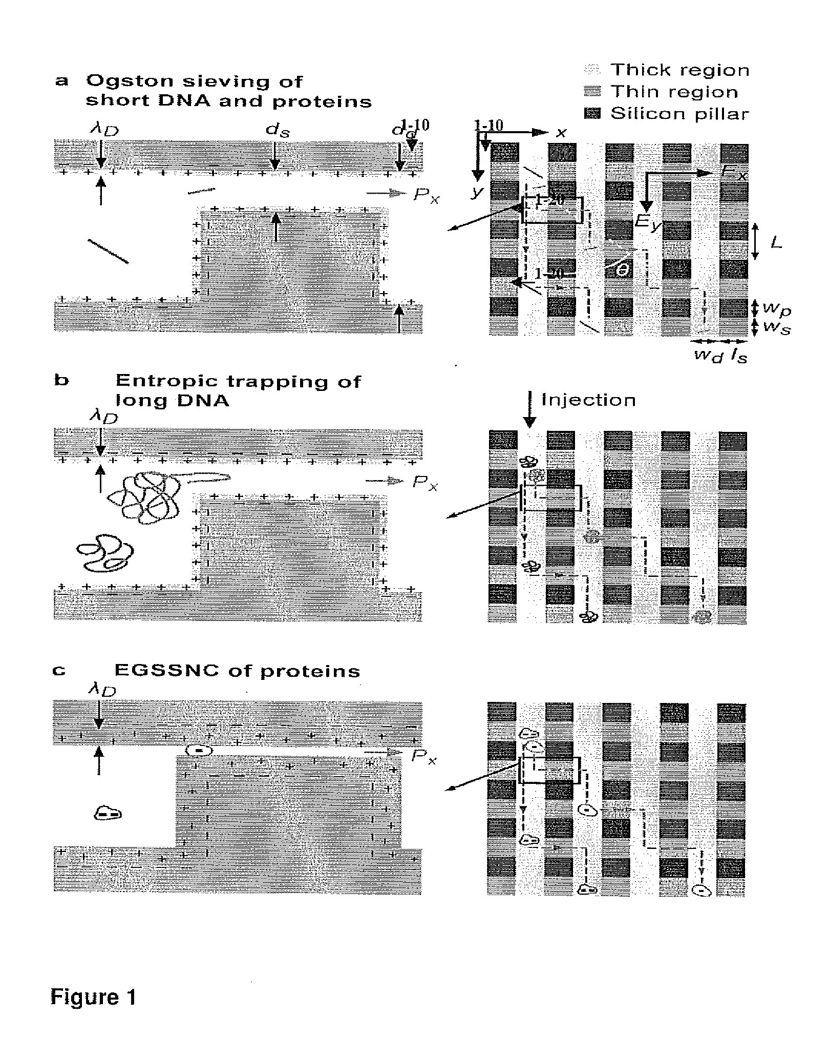
[0161]To construct a device, which can continuously fractionate small biomolecules such as proteins based on their sizes, a nanofilter array chip was fabricated. The microchip comprising nanofilters, representing an embodiment of this inventuion, was constructed using conventional photolithography and reactive ion etching (RIE) techniques, with nanofilter gap thickness (ds) as thin as 20 nm. The microchip was constructed to comprise thick channels (1-10) with width Ld separated by rows of nanofilters (1-20) with width of Ws and length Ls. Rectangle-shaped silicon pillars (1-30) were designed with width of Wp to serve as supporting structures. The rows of nanofilters and silicon pillars may optionally have a lateral shift (FIG. 1A).

[0162]The separation mechanism of the sorter relies on different sieving characteristics along two orthogonal directions within the sorter, which are set perpendicular and parallel to the nanofilter rows (i...

example 2

Operation of the Microseparator in Continuous-Field Mode

[0170]Molecules that can be separated in such a chip include, but are not limited to, proteins and DNA, RNA, carbohydrate (sugar), nanoparticles, and small organelles.

[0171]Optimal sieving with a nanofilter is expected when the molecule size is comparable with the nanofilter thin gap size. However, the gap size of the nanofilter does not have to be smaller than the size of the molecule. Indeed, the separation of SDS-proteins (typically ˜10 nm in physical dimensions) using nanofilters as large as 60 nm is feasible. If one wishes to separate different (larger or smaller) biomoelcules in this chip, nanofilter gap size can be adapted to the molecules to be separated.

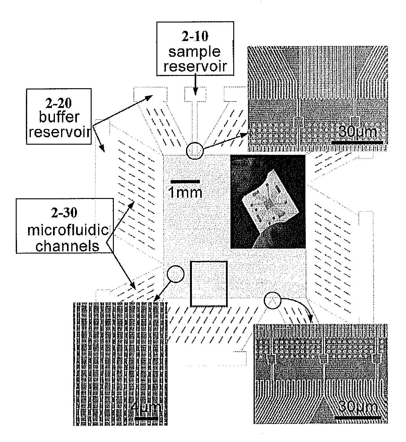
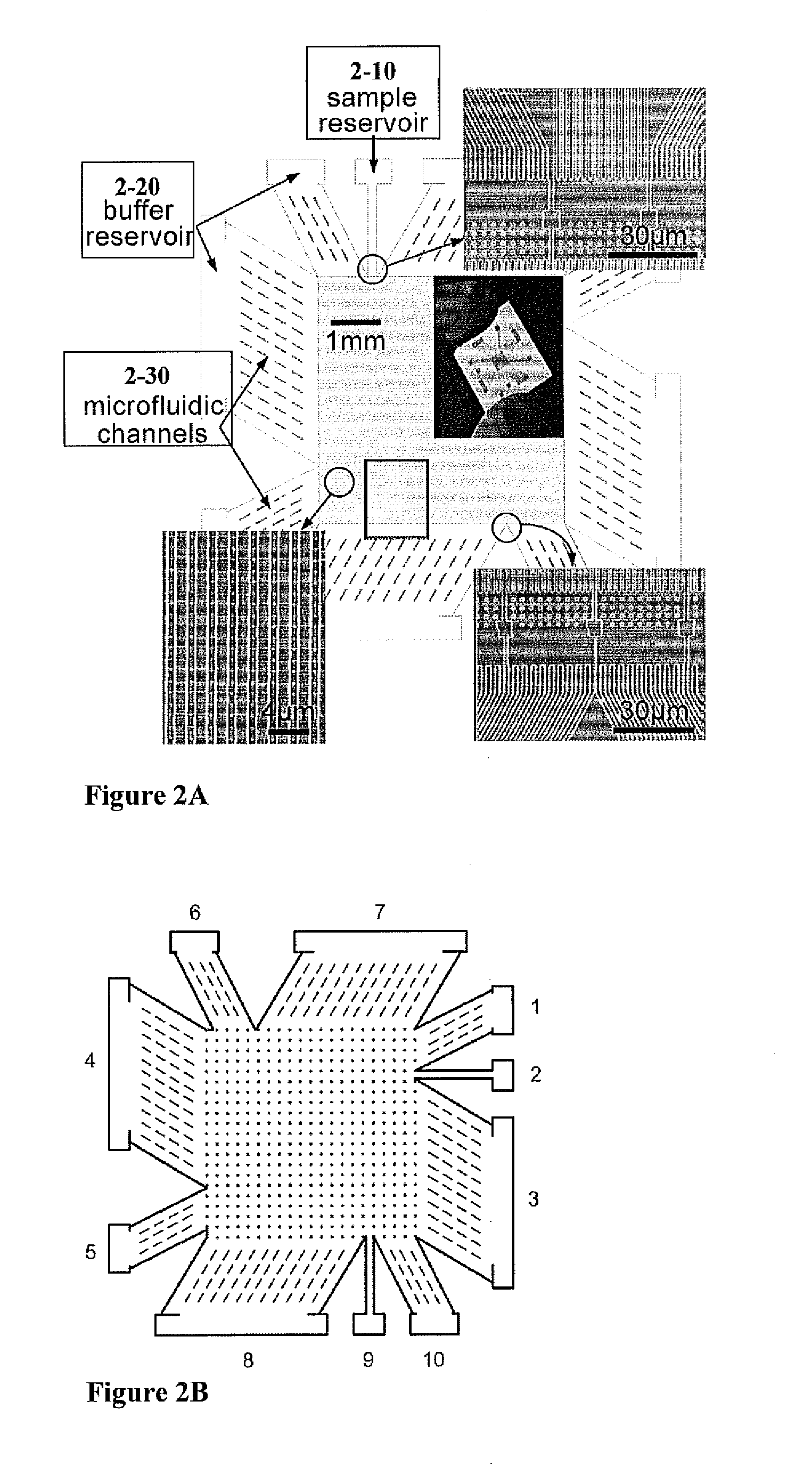
[0172]To demonstrate continuous-flow separation of small biomolecules with the invention of the nanofilter array chip SDS-protein complexes and small double-stranded DNA molecules were separated using a microchip, as depicted in FIG. 2, in continuous field separation mo...

example 3

Operation of the Microseparator in Pulse-Field Separation Mode

[0174]In another embodiment of the microseparator, separation can also be achieved using alternating electric fields of different strengths and / or durations in the pulse-field separation mode (FIG. 4). In the embodiment presented here, the voltage was applied at different reservoirs, where the horizontal electric field (Eh) alternated with the vertical electric field (Ev), and increasing the duration of the vertical force field enhanced the separation. Thus more size-differential jumpings over the nanofilters were experienced in the case of longer duration of the vertical electric field.

[0175]While many different artificial molecular sieving matrixes are known in the art for size-fractionation of biomolecules based on different mechanisms, to date, microfabricated artificial sieving systems have been limited for separation of large biomolecules such as viral DNA, mainly because it is generally challenging to fabricate sie...


PUM

PropertyMeasurementUnit
depthaaaaaaaaaa
depthaaaaaaaaaa
applied voltageaaaaaaaaaa

Abstract

This invention provides a method and an apparatus for quickly continuously fractionating biomolecules, such as DNAs, proteins and carbohydrates by taking advantage of differential bidirectional transport of biomolecules with varying physico-chemical characteristics, for example size, charge, hydrophobicity, or combinations thereof, through periodic arrays of microfabricated nanofilters. The passage of biomolecules through the nanofilter is a function of both steric and electrostatic interactions between charged macromolecules and charged nanofilter walls, Continuous-flow separation through the devices of this invention are applicable for molecules varying in terms of any molecular properties (e.g., size, charge density or hydrophobicity) that can lead to differential transport across the nanofilters.

Description

CROSS REFERENCE TO RELATED APPLICATIONS[0001]This application claims the benefit of U.S. Provisional Application Ser. No. 60 / 723,926, filed Oct. 6, 2005, which is hereby incorporated in its entirety.GOVERNMENT INTEREST STATEMENT[0002]This invention was made in whole or in part with government support under grant number CTS-0347348, awarded by the National Science Foundation. The government may have certain rights in the invention.FIELD OF THE INVENTION[0003]This invention is directed to sorting devices comprising nanoseparation matrices, an apparatus comprising the same, and methods of use thereof for high throughput molecular separations.BACKGROUND OF THE INVENTION[0004]In systems biology, and in the application of biomarker detection and biosensing, the separation and identification of many proteins, small molecules, and carbohydrates from a cell or from complex biological samples, is necessary. Often, one needs to profile the concentrations of many different biomarkers, cytokines...

Claims


Application Information

Patent Timeline
Patent Type & Authority Applications(United States)
IPC IPC(8): G01N27/447G01N27/453B07C5/04
CPCB01D61/027B01L3/502746B01L3/502761B01L2200/0647B01L2300/0864G01N2015/0288B01L2400/0415B01L2400/0487B01L2400/086B82Y30/00B01L2300/0896
Inventor HAN, JONGYOONFU, JIANPING
Owner MASSACHUSETTS INST OF TECH
Why Eureka
Try Eureka