Catalytic Reformer Unit and Unit Operation

a technology of catalyst and unit, applied in the direction of hydrocarbon oil cracking, hydrogen separation using solid contact, separation process, etc., can solve the problems of not being able to achieve the desired effect, increasing the feed rate, and reducing the pressure drop of the circui

Active Publication Date: 2011-06-23
EXXON RES & ENG CO
View PDF18 Cites 9 Cited by
  • Summary
  • Abstract
  • Description
  • Claims
  • Application Information

AI Technical Summary

Benefits of technology

[0006]According to one embodiment, a catalytic naphtha reforming process is carried out by removing hydrocarbons from the hydrogen recycle stream by Conventional Pressure Swing Adsorption (“conventional PSA”). In a preferred embodiment, a catalytic reforming process is carried out by removing hydrocarbons from the hydrogen recycle stream by Rapid Cycle Pressure Swing Adsorption (“RCPSA”). The reduction in the proportion of hydrocarbons in the reformer recycle stream increases the hydrogen purity of the stream, a factor which itself is favorable for the reforming mechanisms, but also from the present point of view, has the advantage of reducing the circuit pressure drop with the result that it becomes possible to overcome the limitation imposed by recycle gas compressor and to increase the feed rate commensurately. The extent to which the compressor limitation may be by-passed will depend on the extent to which the hydrocarbons are removed from the recycle stream: with increasing hydrogen purity, the greater will be the potential increase in naphtha feed rate. Accordingly, it is preferred to increase the hydrogen purity of the recycle stream to at least 85% by volume, preferably to at least 90% by volume, more preferably to at least 95% by volume.
[0007]In a preferred embodiment, a rapid cycle pressure swing adsorption unit is utilized increases the hydrogen content in both the hydrogen-containing recycle stream and the export hydrogen stream of a catalytic reforming unit.

Problems solved by technology
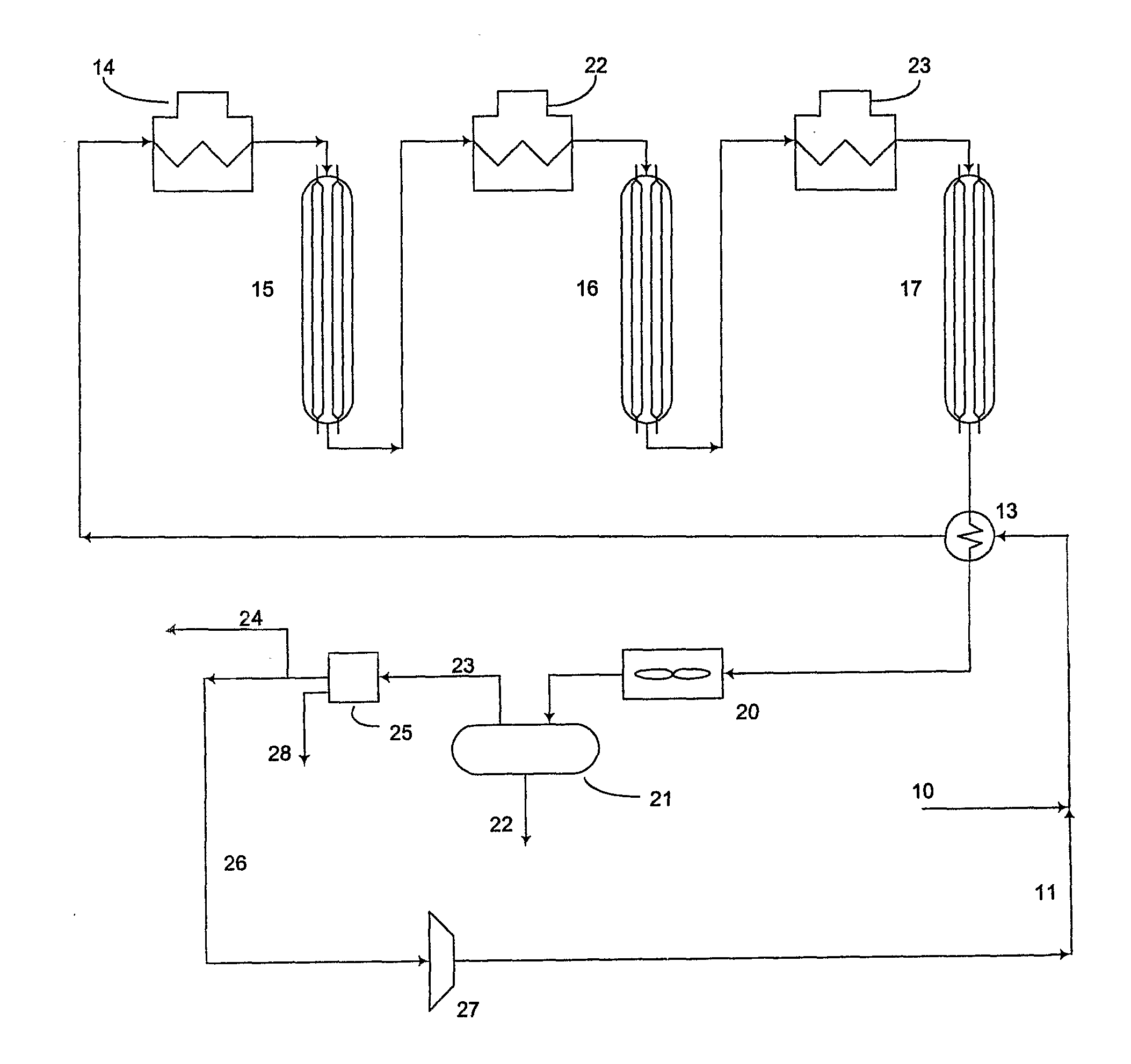
The hydrogen which is has been generated or recycled is not pure and, in fact, typically contains significant quantities of light hydrocarbons which have not been completely removed in the separators which follow the reactor section.
Increasing the pressure may not, however, be desirable in many cases as it will tend to reduce reformate and hydrogen yields, or the unit may already be operating near the maximum design pressure of the equipment.

Method used


Image

  • Catalytic Reformer Unit and Unit Operation

Examples


example 1

[0055]In this example, the refinery stream is at 480 psig with tail gas at 65 psig whereby the pressure swing is 6.18. The feed composition and pressures are typical of refinery processing units such as those found in hydroprocessing or hydrotreating applications. In this example typical hydrocarbons are described by their carbon number i.e. C1=methane, C2=ethane etc. The RCPSA is capable of producing hydrogen at >99% purity and >81% recovery over a range of flow rates. Tables 1a and 1b show the results of computer simulation of the RCPSA and the input and output percentages of the different components for this example. Tables 1a and 1b also show how the hydrogen purity decreases as recovery is increased from 89.7% to 91.7% for a 6 MMSCFD stream at 480 psig and tail gas at 65 psig.

Tables 1a & 1b

Composition (mol %) of Input and Output from RCPSA (67 ft3) in H2 Purification

Feed is at 480 psig, 122 deg F. and Tail Gas at 65 psig. Feed rate is about 6 MMSCFD

[0056]

TABLE 1aHigher puritySt...

example 2

[0058]In this example, the conditions are the same as in Example 1. Table 2a shows conditions utilizing both a co-current and counter-current steps to achieve hydrogen purity >99%. Table 2b shows that the counter-current depressurization step may be eliminated, and a hydrogen purity of 99% can still be maintained. In fact, this shows that by increasing the time of the purge cycle, tP, by the duration removed from the counter-current depressurization step, tCN, that hydrogen recovery can be increased to a level of 88%.

Tables 2a & 2b

Effect of Step Durations on H2 Purity and Recovery from an RCPSA (67 Ft3)

Same Conditions as Table 1. Feed is at 480 psig, 122 deg F. and Tail Gas at 65 psig. Feed Rate is about 6 MMSCFD

[0059]

TABLE 2aWith counter-current depress, Intermediate pressure = 105 psigpurityrecoverytFtCOtCNtPtRP%%sssss98.284.310.2830.050.1670.598.38510.1660.1670.1670.599.98010.0830.250.1670.5

TABLE 2bWithout counter-current depresspurityrecoverytFtCOtCNtPtRP%%sssss97.891.710.33300....

example 3

[0060]This example shows a 10 MMSCFD refinery stream, once again containing typical components, as shown in feed column of Table 3 (e.g. the feed composition contains 74% H2). The stream is at 480 psig with RCPSA tail gas at 65 psig whereby the absolute pressure swing is 6.18. Once again the RCPSA of the present invention is capable of producing hydrogen at >99% purity and >85% recovery from these feed compositions. Tables 3a and 3b show the results of this example.

Tables 3a & 3b

Composition (mol %) of Input and Output from RCPSA (53 Ft3) in H2 Purification. Feed is at 480 psig, 101 deg F. and Tail Gas at 65 psig. Feed Rate is about 10 MMSCFD

[0061]

TABLE 3aHigher purityStep Times in seconds are tF = 0.583, tCO = 0.083, tCN = 0,tP = 0.25, tRP = 0.25H2 at 99.98% purity and 86% recoveryfeedproductTail-GasH274.099.9829.8C114.30.0237.6C25.20.0013.8C32.60.007.4C4+3.90.0011.0H2O2000 vppm0.3 vppm5387 vppmtotal (MMSCFD)10.2206.5143.705480 psig470 psig65 psig

TABLE 3bLower purityStep Times in se...


PUM

PropertyMeasurementUnit
cycle timeaaaaaaaaaa
swing timeaaaaaaaaaa
boilingaaaaaaaaaa

Abstract

An improved process for catalytic reformers and their use for the catalytic reforming of petroleum naphthas. More particularly, the invention relates to an improved reformer unit which can be operated at higher throughput relative to compressor size. The invention utilizes pressure swing adsorption to improve the hydrogen content of hydrogen containing streams generated by and utilized in catalytic reforming processes. The invention also has the capability of enabling compressor-limited catalytic reforming units to be operated at increased capacities.

Description

FIELD OF THE INVENTION[0001]The invention relates generally to catalytic reformers and their use for the catalytic reforming of petroleum naphthas. More particularly, the invention relates to an improved catalytic reformer process which can be operated at higher throughput relative to compressor size. The invention has the capability of enabling compressor-limited reforming units to be operated at greater capacities.BACKGROUND OF THE INVENTION[0002]Catalytic naphtha reforming is an established petroleum refinery process. It is used for improving the octane quality of hydrocarbon feeds in the naphtha boiling range. Generally, reforming refers to the total effect of molecular changes on a hydrocarbon feed, produced by a number of reactions. Typical reforming reactions include dehydrogenation of cyclohexanes, dehydroisomerization of alkylcyclopentanes, dehydrocyclization of paraffins and olefins, isomerization of substituted aromatics, and hydrocracking of paraffins. Typical reforming ...

Claims


Application Information

Patent Timeline
Patent Type & Authority Applications(United States)
IPC IPC(8): C10G35/04C10G35/12C10G35/085
CPCB01D53/0423C10G2300/4081B01D2253/10B01D2253/104B01D2253/106B01D2253/108B01D2256/16B01D2256/24B01D2257/702B01D2259/403C01B3/56C01B2203/042C01B2203/048C10G47/00C10G47/02C10G47/18C10G47/20C10G2300/1044B01D53/0473
Inventor GOLDSTEIN, STUART S.THURTOLL, JOHN H.KAUL, BAL K.MARSHALL, GREG A.
Owner EXXON RES & ENG CO
Why Eureka
Try Eureka