Membrane electrode assembly fabrication

a technology of membrane electrodes and assembly, which is applied in the direction of cell components, electrochemical generators, chemistry apparatus and processes, etc., can solve the problems of insufficient mass production of fuel cells, difficult scaling up to high-rate production, and inconvenient use of cvd, pvd and ecd methods in fuel cells with gas phase fuel. achieve the effect of reducing production costs and ensuring mass production

Inactive Publication Date: 2011-07-07
ALTERGY SYST
View PDF20 Cites 2 Cited by
  • Summary
  • Abstract
  • Description
  • Claims
  • Application Information

AI Technical Summary

Benefits of technology

[0019]It is an object of this invention is to provide a method for fabricating MEAs employing such gas diffusion layers and or gas diffusion electrodes that address the problems attendant to conventional methods as discussed hereinabove. Due to the mechanically unstable nature of the electrolyte membrane material, it is advantageous to attach or bond the electrolyte membrane material to a supportive substrate before being sized for incorporation into a fuel cell. In the case of the instant invention, this takes the form of using the GDL or GDE as the supportive substrate. By the use of this invention, MEAs can be more readily mass produced and therefore produced at lower costs than hand assembled products that are heretofore the norm.

Problems solved by technology

Too little water causes a high internal resistance due to low humidification of the polymeric membrane while too much water causes flooding of the fuel cell by the water.
However, some of these methods are very difficult to scale up to high rate production to fabricate gas diffusion electrodes with good surface conductivity, gas permeability, uniformity, and long-term hydrophobic and hydrophilic stability.
The CVD, PVD and ECD methods are not useful in a fuel cell with a gas phase fuel because these methods cannot deposit the electrolyte ionomer with the catalyst particles, as a result of which there is no electrolyte between the catalyst particles in the gas phase.
This cutting to size and subsequent handling is problematic due to the nature of the electrolyte membrane itself, it being on the order of 10 micrometers to 100 micrometers thick and sensitive to changes in humidity which can cause it to change dimensions and shape.
Although resulting in good contact between the catalyst layer and the electrolyte membrane, this method is limited to producing only small electrodes due to the problem of catalyst releasing from the substrate.
In addition, it is very difficult to scale up for mass production.

Method used


Image

  • Membrane electrode assembly fabrication
  • Membrane electrode assembly fabrication
  • Membrane electrode assembly fabrication

Examples


first embodiment

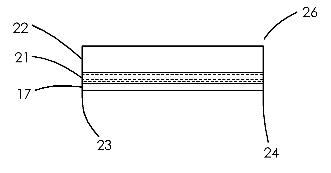
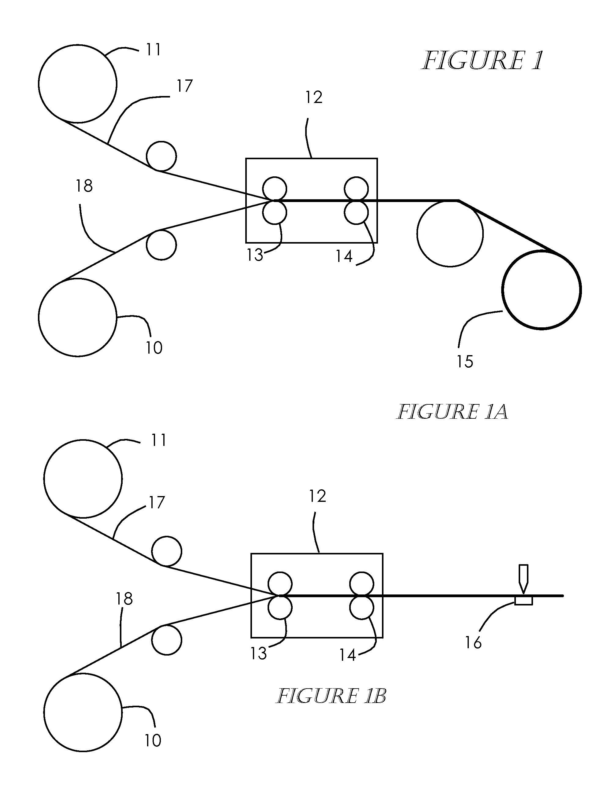
[0041]A precursor-MEA is produced in accordance with this invention by attaching or bonding a polymer electrolyte membrane to a gas diffusion layer by one of two preferred embodiments. FIGS. 1A and 1B show a first embodiment, gas diffusion electrode material (GDE) 18 such as that supplied by the E-TEK Division of PEMEAS Fuel Cell Technologies on a roll 10 is mated or bonded with a polymer electrolyte membrane material 17 such NAFION® by DuPont, also supplied on a roll 11, forming a unified structure. The GDE material can preferably be a cathode but can alternately be an anode. The two materials are unwound and roll bonded or laminated with the use of heat 12 at a temperature of about 50 C. to 200 C. and pressure 13, 14 of about 50 psi to 300 psi in such a manner that the catalyst / electrode side of the GDE is in contact with the polymer electrolyte membrane material. The temperature and pressure make the ionomer in the catalyst layer soft and adhesive to provide a good bond between t...

second embodiment

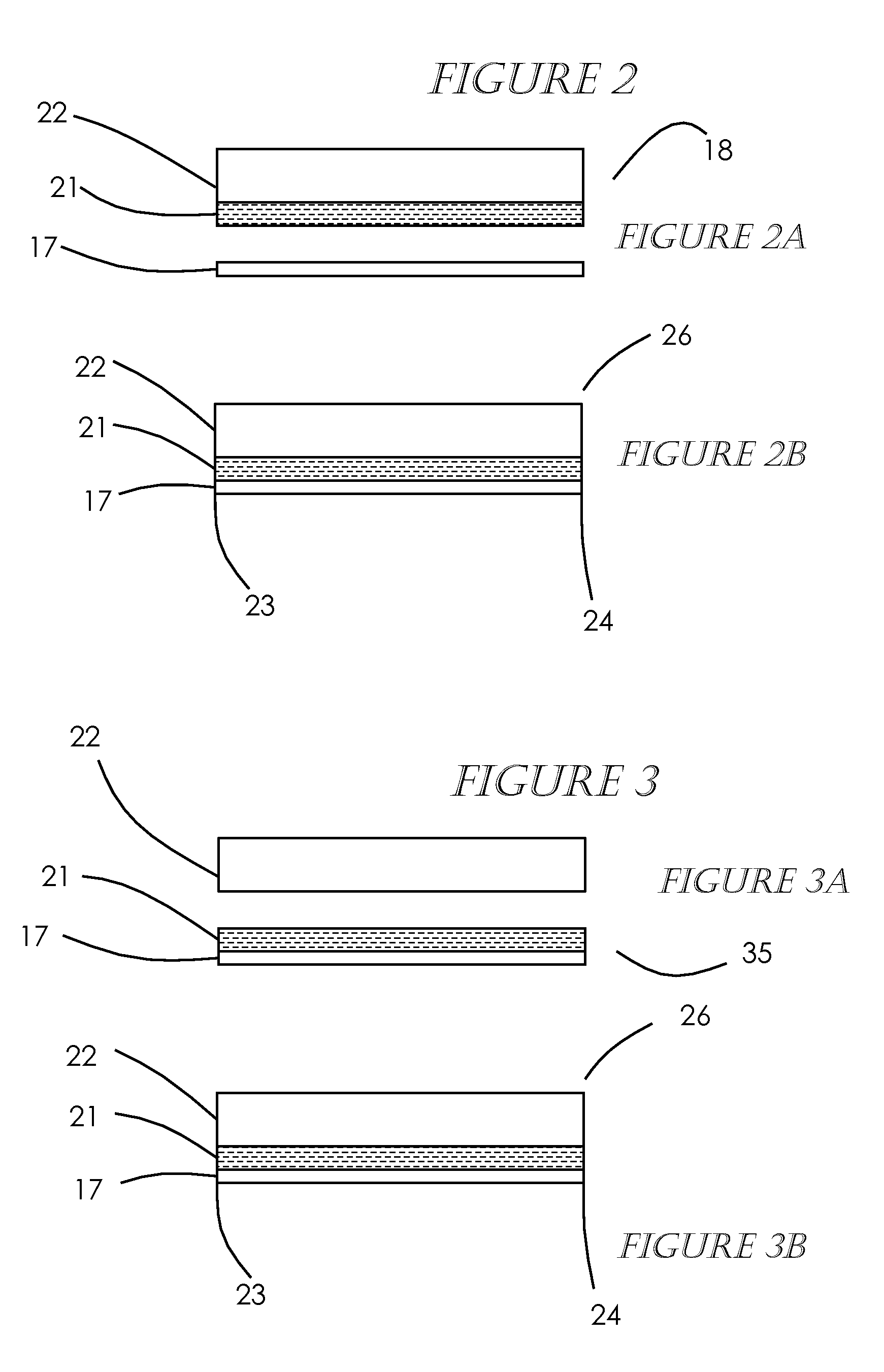
[0042]the method of producing the precursor-MEA, shown in FIGS. 3A-3B, is to use a polymer electrolyte membrane 17 onto which a catalyst / electrode 21 has been applied / bonded to one side of the polymer electrolyte membrane material, forming a 2-layer MEA 35 having the electrolyte membrane material 17 with the catalyst / electrode 21 essentially covering the entire one side of the electrolyte membrane material 17, with no need for borders or frames as is the usual practice. The 2-layer MEA 35 can preferably be a cathode but can alternately be an anode. U.S. Pat. Nos. 6,197,147; 6,933,033; and 6,855,178 teach methods of applying a catalyst / electrode to a polymer electrolyte membrane. Polymer electrolyte material with catalyst / electrodes bonded on is supplied by DuPont, W. L. Gore, and Ion Power, among others. Gas diffusion layer material (GDL) 22 such as that supplied by the E-TEK Division of PEMEAS Fuel Cell Technologies, Toray Industries, Inc. and SGL Carbon AG on a roll 40 is mated or...


PUM

PropertyMeasurementUnit
thickaaaaaaaaaa
pressureaaaaaaaaaa
dimensionsaaaaaaaaaa

Abstract

A method for fabricating MEAs employing such gas diffusion layers and or gas diffusion electrodes that address the problems attendant to conventional methods. Due to the mechanically unstable nature of the electrolyte membrane material, it is advantageous to attach or bond the electrolyte membrane material to a supportive substrate before being sized for incorporation into a fuel cell. The GDL or GDE is used as the supportive substrate for the electrolyte membrane material.

Description

CROSS-REFERENCE TO RELATED APPLICATIONS[0001]This application is a divisional of U.S. patent application Ser. No. 11 / 516,948 filed on Sep. 6, 2006, incorporated herein by reference in its entirety.STATEMENT REGARDING FEDERALLY SPONSORED RESEARCH OR DEVELOPMENT[0002]Not ApplicableINCORPORATION-BY-REFERENCE OF MATERIAL SUBMITTED ON A COMPACT DISC[0003]Not ApplicableNOTICE OF MATERIAL SUBJECT TO COPYRIGHT PROTECTION[0004]A portion of the material in this patent document is subject to copyright protection under the copyright laws of the United States and of other countries. The owner of the copyright rights has no objection to the facsimile reproduction by anyone of the patent document or the patent disclosure, as it appears in the United States Patent and Trademark Office publicly available file or records, but otherwise reserves all copyright rights whatsoever. The copyright owner does not hereby waive any of its rights to have this patent document maintained in secrecy, including wit...

Claims


Application Information

Patent Timeline
Patent Type & Authority Applications(United States)
IPC IPC(8): B32B38/10B32B37/00
CPCH01M4/881H01M4/8896Y10T156/1074H01M8/1004Y02E60/521H01M4/926Y02E60/50
Inventor DABEL, JEREMY W.FRANKLIN, JERROLD E.
Owner ALTERGY SYST
Why Eureka
Try Eureka