Nanowires and Method for the Production there of

a technology of nanowires and nanoparticles, applied in the field of nanowires, can solve the problems of loss of contact between nanoparticles, major problem in the stabilization of these, limited catalyst surface of the reactor, etc., and achieve the effect of stable nanowire structural elements

Inactive Publication Date: 2011-07-21
GSI HELMHOLTZZENT FUR SCHWERIONENFORSCHUNG
View PDF9 Cites 21 Cited by
  • Summary
  • Abstract
  • Description
  • Claims
  • Application Information

AI Technical Summary

Benefits of technology

[0036]In general, with the template based process using a template foil allows for numerous nanowires to be produced at the same time. After their production, they can be separated from one another through the removal of the cathode layer such that numerous individual segmented nanowires are obtained.
[0037]It is however also advantageous to produce a stable nanowire structural element having an array of many of the segmented nanowires. This can be accomplished, for example, wherein the cathode layer remains as a substrate layer of the nanowire array and wherein each nanowire is integrally formed with the substrate layer. For this, the template foil is dissolved without removing the cathode layer first. In this case, the cathode layer serves a double purpose; on one hand it serves as an electrode for the electrochemical deposition procedure and on the other hand is serves as a stable, closed substrate or cover layer for the completed nanowire structural element, i.e. it remains as an integral component of the nanowire structural element which is to be produced, and is not removed from said. It is, however, conceivable that after the deposition of the nanowires in the nanopores, the cathode layer is removed and a new cover layer is applied.

Problems solved by technology

This means however that the catalytic surface is limited to the walls of the reactor.
The stabilization of these is a major problem.
1. Loss of contact between nanoparticles due to corrosion of the carrier.
2. Dissolving and renewed deposition or Ostwald ripening.
3. Aggregation of the nanoparticles in order to minimize the surface energy.
4. Dissolving of the nanoparticles and migration of the dissolvable ions.

Method used


Image

  • Nanowires and Method for the Production there of
  • Nanowires and Method for the Production there of
  • Nanowires and Method for the Production there of

Examples


example 1

n of a Nanowire Structural Element with Parallel Nanowires

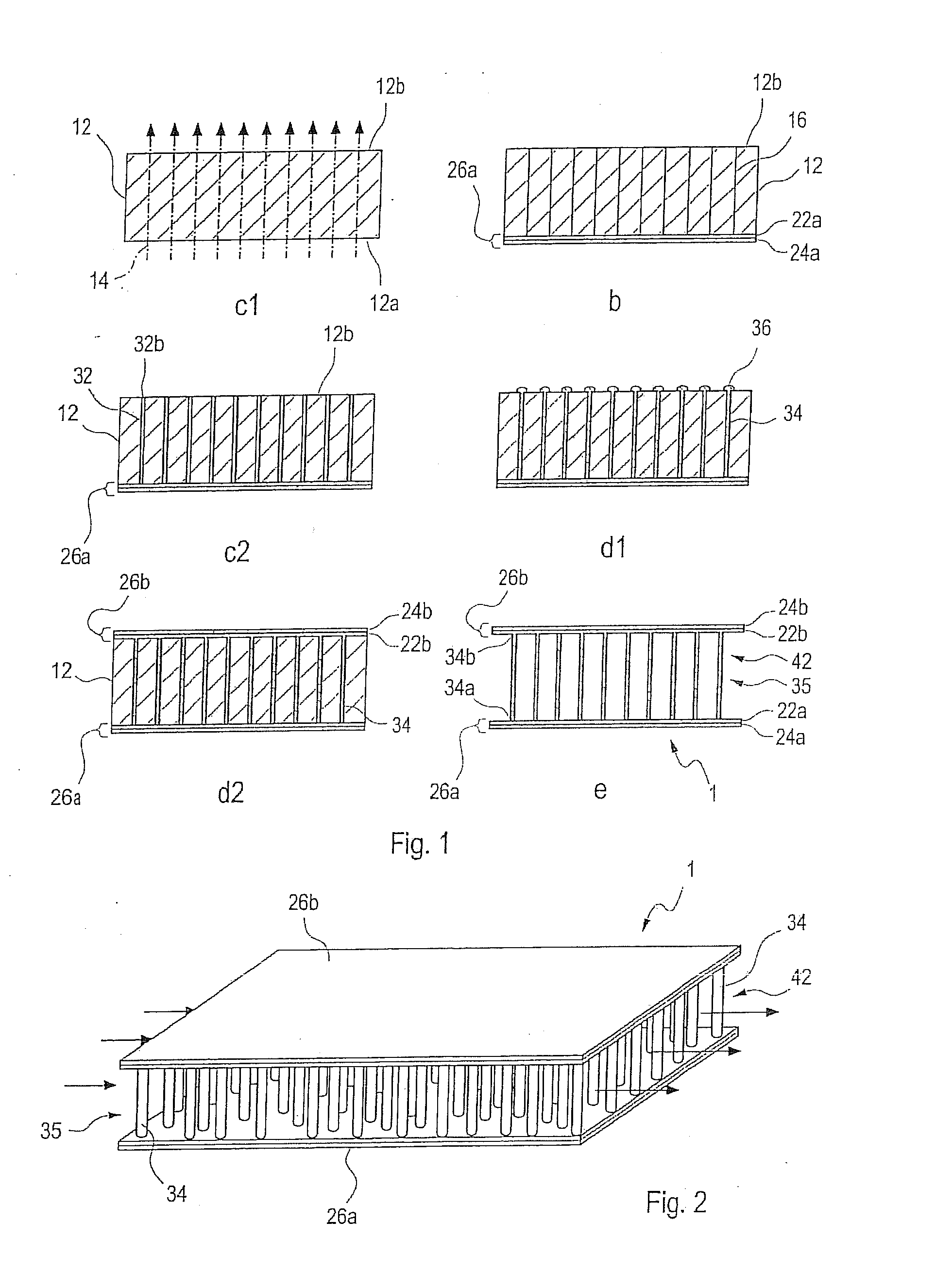
[0082]The production of nanowire structural elements is based on a template based process. The partial steps of the process are schematically presented in FIG. 1 as follows:

[0083](c1) Bombardment of the template foil with ions,

[0084](b) Application of a conductive layer,

[0085](c2) Etching of the ion tracks to form nanopores,

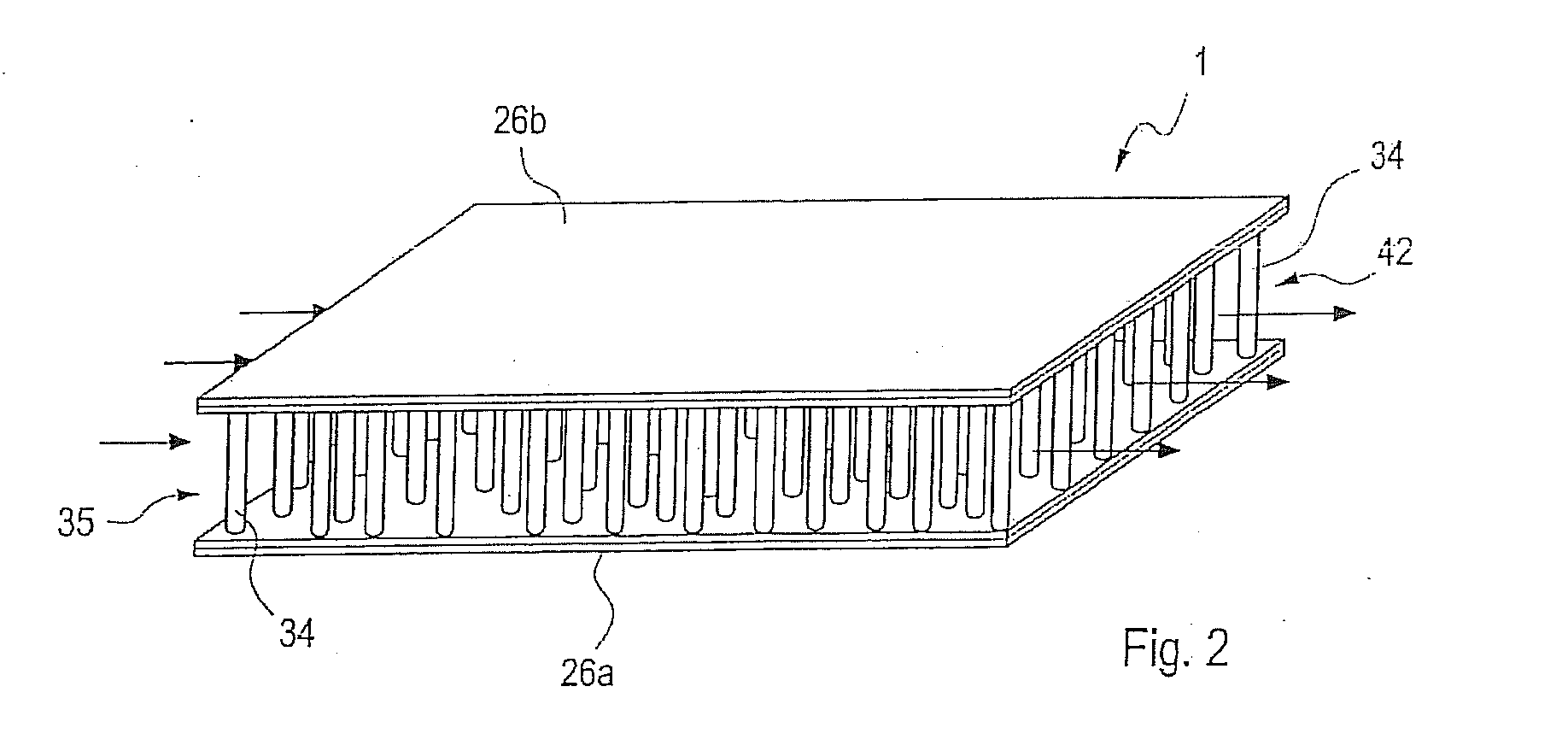
[0086](d1) Deposition of the nanowires and development of the caps,

[0087](d2) Deposition of the second metal layer,

[0088](e) Dissolving of the template.

[0089]Preferably the process steps are carried out in the sequence shown in FIG. 1, i.e. (c1), (b), (c2), (d1), (d2), (e). It is however possible to use a different sequence, e.g. to etch from two sides and then subsequently first apply the cathode layer partial layer ((c2) before (b)). (See, for example, FIG. 3).

[0090]With reference to FIG. 1, first a template foil 12 is bombarded with ions 14, wherein latent ion tracks 16 are generated in the substance of...

example 2

n of a Nanowire Structural Element with an Cross-Linked Nanowire Array

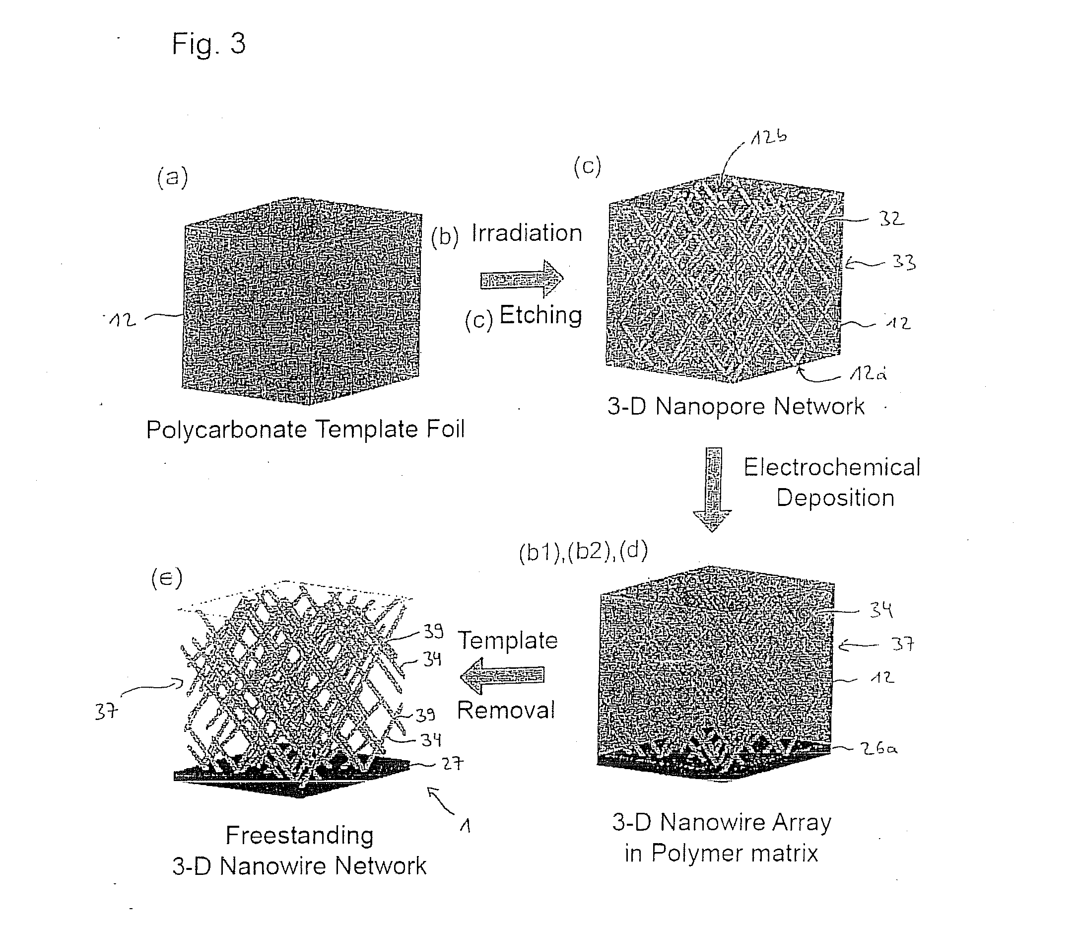
[0101]FIG. 3 schematically shows the production of a nanowire structural element with an interconnected nanowire array. For this, the template foil 12 is irradiated from numerous different angles with ions such that the latent tracks and later the intersecting nanopores, or respectively, the intersecting nanowires run at an angle, for example, 90°, to each other. It is to be understood that other angles are also possible.

[0102]For successive irradiation of the template foil 12 at various angles, the template foil 12 is first positioned in a corresponding jet tube at a first angle to the direction of the ion beam, e.g. in the synchrotron of the GSI, and irradiated with a predefined first ion surface density. Subsequently the template foil 12 is tilted in relation to the beam direction and again irradiated with a predefined second ion surface density. If nanowires are to be generated at more angles, the procedure is...

example 3

n of Individual Nanowires

[0104]Although it is preferred that a nanowire structural element 1, as is described based on FIG. 1 or FIG. 3, it is however, basically possible as well, to produce individual segmented nanowires 34. A schematic presentation of the production steps is shown in FIG. 4. In this case, the electrochemical deposition is arrested before the development of caps begins (d1) and subsequently the cathode layer 26a is removed. This is particularly possible if the cathode layer 26a or at least the first partial layer 22a consists of a different material than the nanowires 34. The template foil 12 is subsequently dissolved in a step (e) thus causing the individual nanowires 34 to separate (not shown).

Exemplary Parameters for the Production of the Segmenting of the Nanowires

[0105]All of the examples described in the preceding are produced with segmented nanowires 34 in accordance with this invention.

[0106]For example, a 30 μm thick, a circular shaped (r=1.5 cm) polycarbo...


PUM

PropertyMeasurementUnit
equilibrium voltageaaaaaaaaaa
negative absolute voltageaaaaaaaaaa
lengthaaaaaaaaaa

Abstract

The invention concerns the production of segmented nanowires and components having said segmented nanowires.
For the production of the nanowire structural element, a template based process is used preferably, wherein the electrochemical deposition of the nanowires in nanopores is carried out. In this manner, numerous nanowires are created in the template foil.
For the electrochemical deposition of the nanowires, a reversed pulse procedure with an alternating sequence consisting of cathodic deposition pulses and anodic counter-pulses is carried out. By this means, segmented nanowires can be produced.

Description

FIELD OF THE INVENTION[0001]The invention concerns nanowires with a special structure, a process for production of said as well as components made of these nanowires.BACKGROUND OF THE INVENTION[0002]In “Chemistry in Microstructured Reactors,” Ang. Chem. Int. Ed. 2004, 43, 406-466 [: Applied Chemistry, International Edition], K. Jahnisch et al. have demonstrated the advantages that microstructured components have in chemical reactions and for analytical purposes. This has led to an increase in the importance that such systems have for chemical synthesis and analysis. In comparison to conventional reactors, these microstructures have a large surface area / volume ratio, which has a positive influence on the transference of heat as well as the process of the transportation of matter (see also: O. Wörz et al. “Micro-reactors—A New Efficient Tool for Reactor Development,” Chem. Eng. Technol. 2001, 24, 138-142).[0003]Many known reactions have been carried out in microstructure reactors, inc...

Claims


Application Information

Patent Timeline
Patent Type & Authority Applications(United States)
IPC IPC(8): G01F1/688C25D5/02C25D7/06B32B3/26B01J19/00B82Y99/00
CPCB01J19/0093Y10T29/49117B01J23/72B01J35/0006B01J2219/00783B01J2219/00835B01J2219/00846B01J2219/00853B01J2219/0086B01J2219/00873B22F1/0025B22F3/002B81B2201/0292B81B2201/051B81C99/0085B82Y15/00B82Y30/00C25D1/04C25D1/08C25D5/18C25D1/00C25D1/003Y10S977/762B82Y40/00C25D1/006Y10T428/12201Y10T428/24562Y10T428/25B01J23/42Y10T428/12389Y10T428/24893C25D5/617B22F1/0547G01F1/688G01N25/00
Inventor CORNELIUS, THOMASENSINGER, WOLFGANGNEUMANN, REINHARDRAUBER, MARKUS
Owner GSI HELMHOLTZZENT FUR SCHWERIONENFORSCHUNG
Why Eureka
Try Eureka