Electrochemical reactor, method for manufacturing the electrochemical reactor, gas decomposing element, ammonia decomposing element, and power generator
a technology for electrochemical reactors and gas decomposing elements, applied in the direction of sustainable manufacturing/processing, physical/chemical process catalysts, separation processes, etc., can solve problems such as human harm, and achieve the effects of low running cost, high throughput capacity, and small siz
- Summary
- Abstract
- Description
- Claims
- Application Information
AI Technical Summary
Benefits of technology
Problems solved by technology
Method used
Image

Examples
first embodiment
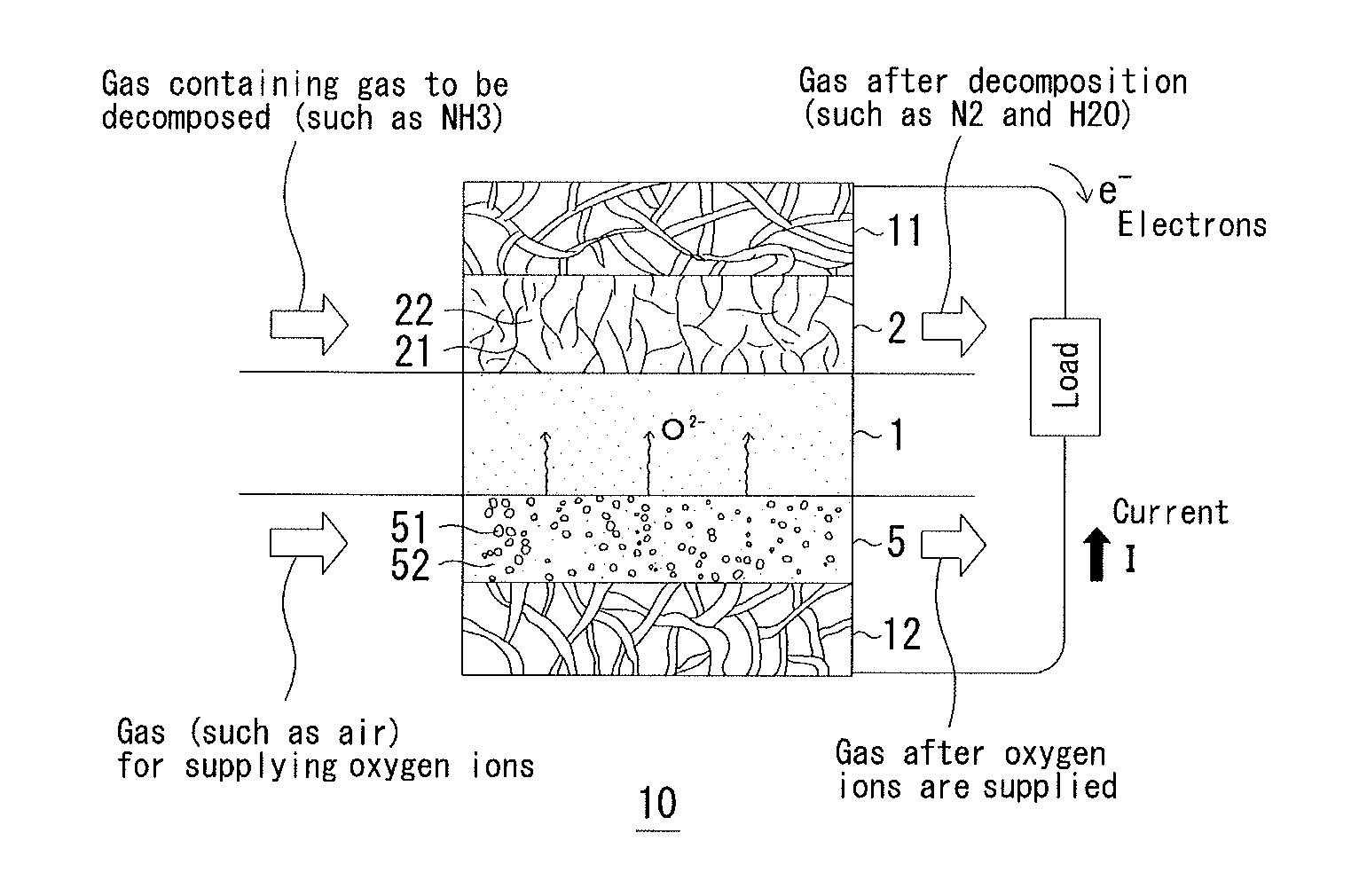
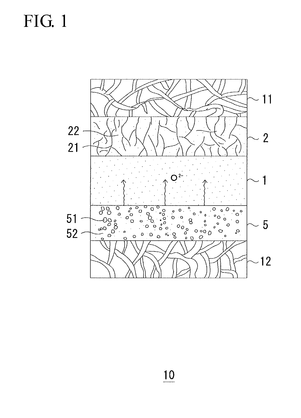
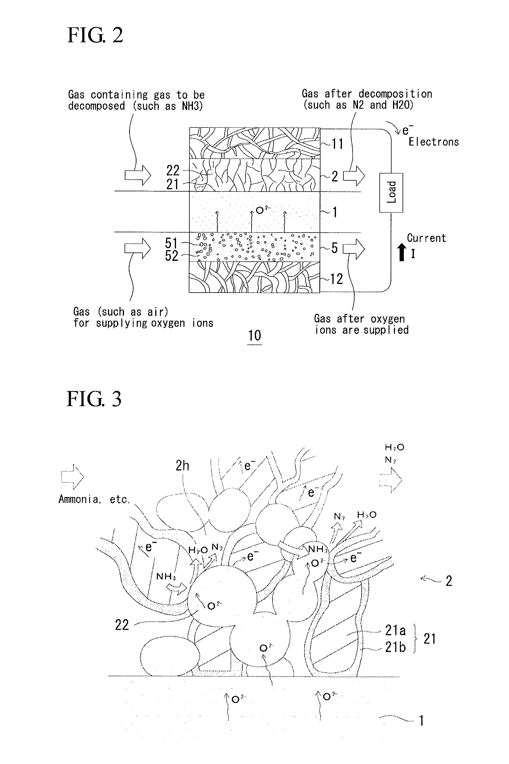
[0082]FIG. 1 is a diagram showing a gas decomposing element 10 according to a first embodiment of the present invention. In the gas decomposing element 10, an anode 2 and a cathode 5 are disposed with an ion conductive electrolyte 1 therebetween. An anode collector 11 is provided on the outer side of the anode 2, and a cathode collector 12 is provided on the outer side of the cathode 5. The anode 2 is a sintered body mainly constituted by metal particle chains 21 and an ion conductive ceramic (metal oxide) 22 and is a porous body in which a fluid can be distributed. The cathode 5 is also a porous body in which a fluid can be distributed. The cathode 5 is preferably a sintered body mainly constituted by silver (Ag) 51 and an ion conductive ceramic 52. Both the anode collector 11 and the cathode collector 12 are preferably a porous metal body. An example of the porous metal body is a metal porous body including trigonal prism skeletons three-dimensionally aligned and having continuous...
second embodiment
[0105]FIG. 5 is a diagram showing a gas decomposing element according to a second embodiment of the present invention. In general, the reaction in this embodiment is an electrolytic reaction as shown by R5, R7, and R8 in Table I. In other words, the gas decomposing element 10 is an electrolyzing element and decomposes gas (in particular, NOx in the case of FIG. 5) by injecting electric power. Air is introduced into the anode 2 and NOx is introduced into the cathode 5. Although the gas to be decomposed is introduced to the anode 2 in the first embodiment, the gas to be decomposed is introduced into the cathode 5 in this embodiment. The anode reaction is 2O2−→O2+4e−. The cathode reaction in the case of NO is 2NO+4e−→N2+2O2−. A potential difference (voltage) is applied from the outside between the collector 11 of the anode 2 and the collector 12 of the cathode 5 so that the potential of the anode is higher. The external power source consumes the electric power for the gas decomposition...
third embodiment
[0109]FIG. 6 is a diagram showing a gas abatement device, which is an electrochemical reactor of a third embodiment of the present invention, in particular, an ammonia decomposing device 10. According to the ammonia decomposing device 10, an anode (first electrode) 2 covers the inner surface of a cylindrical solid electrolyte 1, and a cathode (second electrode) 5 covers the outer surface to form a cylindrical MEA7 (1, 2, 5). In general, the cylindrical body may be twisted into, for example, a spiral shape or a serpentine shape, but the MEA shown in FIG. 6 has a straight cylindrical shape. According to the electrochemical reactor 10 of this embodiment, a porous metal body 11 is disposed to fill the inner cylinder of the cylindrical MEA 7. The inner diameter of the cylindrical MEA is, for example, about 20 mm and may be changed depending on the device applied.
[0110]This embodiment features that the MEA 7 has a cylindrical shape. Because the MEA 7 has a cylindrical shape, it is suffici...
PUM
| Property | Measurement | Unit |
|---|---|---|
| temperature | aaaaa | aaaaa |
| temperature | aaaaa | aaaaa |
| decomposition reaction rate | aaaaa | aaaaa |
Abstract
Description
Claims
Application Information
 - R&D
- Intellectual Property
- Life Sciences
- Materials
- Tech Scout
- Unparalleled Data Quality
- Higher Quality Content
- 60% Fewer Hallucinations
Browse by: Latest US Patents, China's latest patents, Technical Efficacy Thesaurus, Application Domain, Technology Topic, Popular Technical Reports.
© 2025 PatSnap. All rights reserved.Legal|Privacy policy|Modern Slavery Act Transparency Statement|Sitemap|About US| Contact US: help@patsnap.com