Gas purification processes

a technology of gas purification and process, applied in the field of gas purification processes, can solve the problems of high energy requirements for purifying renewable methane, high capital and operating costs, and high cleanup costs of biogas/landfill gas, etc., to reduce the need for buffer tanks, facilitate flare operation or use, and reduce the effect of capital and operating costs

Inactive Publication Date: 2011-08-04
LINDE AG
View PDF7 Cites 72 Cited by
  • Summary
  • Abstract
  • Description
  • Claims
  • Application Information

AI Technical Summary

Benefits of technology

[0016]Both systems can be continuous adsorption methods like a rotating bed PSA / VSA, or a rotary valve PSA / VSA. Any combination of regenerative adsorption techniques should be covered. These have a significant advantage in that they eliminate or reduce the need for buffer tanks, allow for easier controls and plant operation and more stable waste flows that facilitate flare operation or use in an engine for power generation. The waste flows from the plant are stable and continuous and more readily flared. Additionally, the waste stream can be combined with additional biogas / landfill gas for power generation.
[0017]The guard bed is typically granular activated carbon (GAC), but can include other sacrificial layers to remove halogenated compounds, trace heavy metals and residual siloxanes. Sometimes, chilling is used in conjunction with this for higher capacity or more effective contaminant removal.
[0018]Chilling can also be used upstream of the first PSA to lower the water and VOC load on the unit so that it can produce cleaner gas and / or have greater cleanup capacity.

Problems solved by technology

Further, the energy that is required to purify the renewable methane is significant.
The cleanup of biogas / landfill gas is both capital and power intensive because it contains a large number of trace and bulk contaminants in fairly large concentrations.
However, these processes can be expensive in both capital and operating costs and it is important to minimize these costs to achieve an economically viable process.
LNG production is particularly challenging since all condensable contaminants including carbon dioxide must be removed to low ppm levels.

Method used


Image

  • Gas purification processes
  • Gas purification processes
  • Gas purification processes

Examples


Embodiment Construction

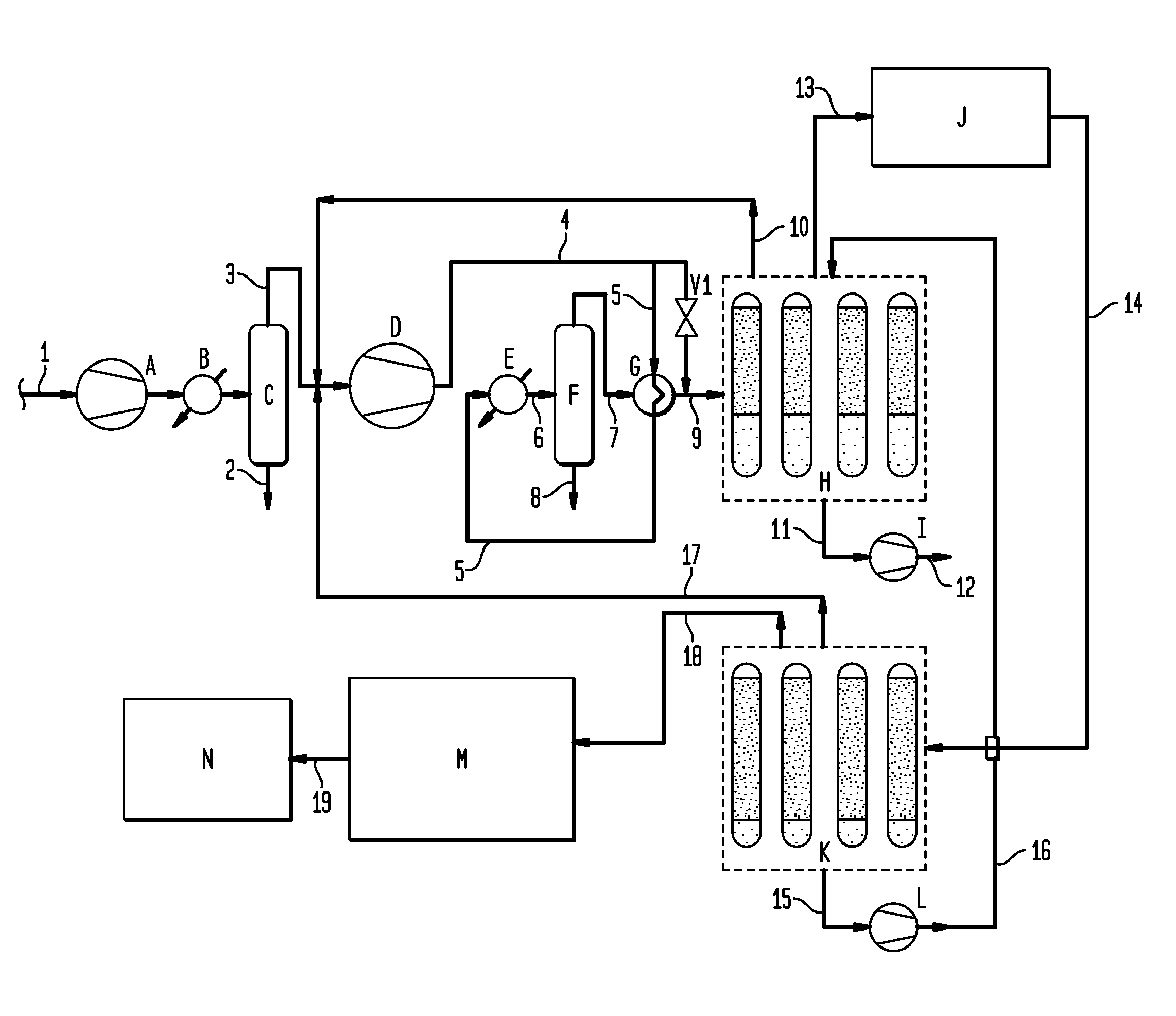
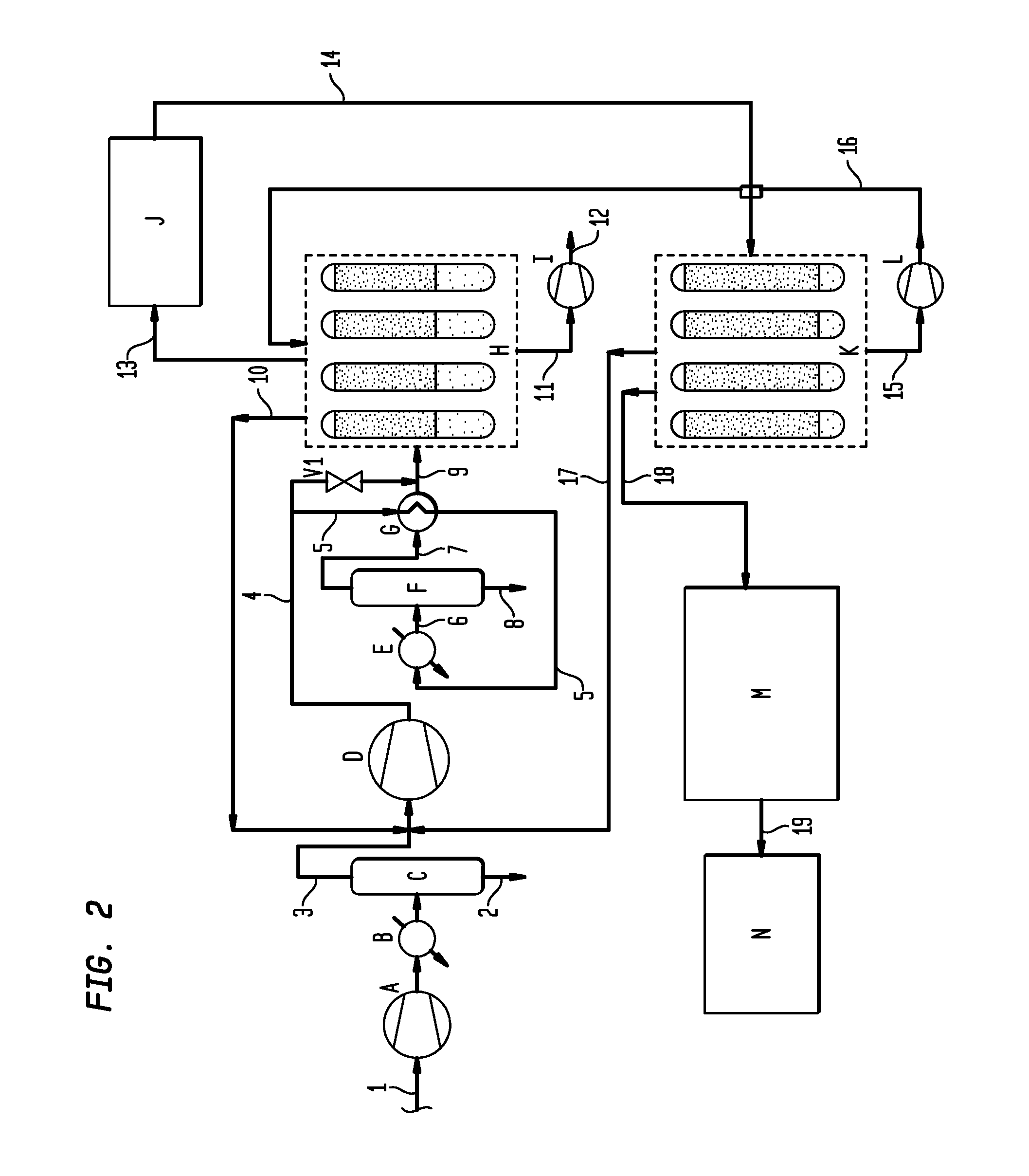
[0027]FIG. 2 is a schematic of a gas purification system having two adsorption units. Raw landfill gas is fed through line 1 into a feed blower A and through heat exchanger B into condenser C. Condensate is removed from the condenser C through line 2 and the gas stream exiting the condenser C through line 3 enters feed compressor D. The landfill gas is primarily composed of methane gas but contains a variety of contaminants, including water. The condenser will assist in removing water and non-methane organic compounds (NMOCs).

[0028]The landfill gas stream will exit the feed compressor D at a pressure of 80 to 250 psig through line 4 and valve V1 to contact line 9 which enters the first adsorption unit H. The compressed landfill gas stream may also enter line 5 through heat exchanger G before entering heat exchanger E and is directed through line 6 to a condenser F where condensate will be removed by line 8 and the gaseous portion fed through line 7 into G and line 9 into the first a...


PUM

PropertyMeasurementUnit
pressureaaaaaaaaaa
adsorptionaaaaaaaaaa
pressureaaaaaaaaaa

Abstract

A method for removing contaminants from a natural gas stream such as a biogas/landfill gas stream. The natural gas stream is fed to a first adsorption unit for removal of certain contaminants and then to a second adsorption unit for the removal of additional contaminants. Alternatively, a membrane stage may be employed between the adsorption units. The method utilizes the external purge to enhance pressure swing adsorption working capacity so that the vacuum level required for regeneration is not as high.

Description

CROSS REFERENCE TO RELATED APPLICATIONS[0001]The present application claims priority from U.S. Provisional Patent Application 61 / 300,501, filed Feb. 2, 2010.BACKGROUND OF THE INVENTION[0002]The invention provides for a method for purifying natural gas. More particularly the invention provides for purifying biogas including digester gas and biogas from wastewater facilities and / or landfill gas.[0003]Renewable methane can be recovered from a number of sources, such as anaerobic digestion of municipal or industrial waste streams, the degradation of biomass in landfills, or the gasification of waste and biomass streams, amongst others. In many instances, this renewable methane require purification before it can be used and / or sold into higher valued markets, such as injection into the pipeline grid, as a feedstock for liquefied natural gas (LNG), as a vehicle fuel, or as a feedstock for the production of hydrogen. Further, the energy that is required to purify the renewable methane is s...

Claims


Application Information

Patent Timeline
Patent Type & Authority Applications(United States)
IPC IPC(8): B01D53/00B01D53/02B01D53/047B01D53/22B01D53/46
CPCB01D53/002C12M47/18B01D53/228B01D53/229B01D53/75B01D2253/102B01D2253/104B01D2253/106B01D2253/108B01D2253/116B01D2256/24B01D2257/102B01D2257/104B01D2257/304B01D2257/504B01D2257/55B01D2257/702B01D2257/80B01D2258/05B01D2259/40052B01D2259/402B01D2259/404B01D2259/4146C10L3/101C10L3/103C10L3/104C10L3/106Y02C10/08Y02C10/10Y02E50/346B01D53/0476Y02P20/59Y02C20/40Y02E50/30
Inventor SETHNA, RUSTAMTIETJEN, RUSSECKHARDT, STEVE
Owner LINDE AG
Why Eureka
Try Eureka