Processing method

Inactive Publication Date: 2011-08-11
CANON KK
View PDF28 Cites 4 Cited by
  • Summary
  • Abstract
  • Description
  • Claims
  • Application Information

AI Technical Summary

Benefits of technology

[0011]Light intensity distribution corresponding to a processing shape does not need to be formed. Therefore, complicated optical system and apparatus are not necessary and it becomes possible to suppress light loss to be small. In an upper limit of light energy of a laser source, the processing area can be widely obtained as much as possible; and therefore, the utilization efficiency of light energy can be maximized and the processing speed can be increased.
[0012]Because processing is performed by using an ultrashort pulse laser whose thermal influence is minimal, a shape with high accuracy can be obtained.

Problems solved by technology

It is known that general laser processing utilizes the effect by thermogenesis due to light absorption; however, in the case of using an ultrashort pulse laser, non-thermal processing is possible.
However, in the case of performing microscopic and high quality processing by ultrashort pulse laser light, the irradiation energy is required to set to energy near to a processing threshold.
Therefore, there is an unsolved problem in that energy output from a laser source cannot be sufficiently and effectively used.
Actually, a pulse effective for processing is very limitative, and this method cannot sufficiently utilize the energy of a laser source.
However, a diffraction phase grating for diverging of a beam needs to be made for each shape, and a loss of light energy is produced by the diffraction phase grating.

Method used


Image

  • Processing method
  • Processing method
  • Processing method

Examples


example 1

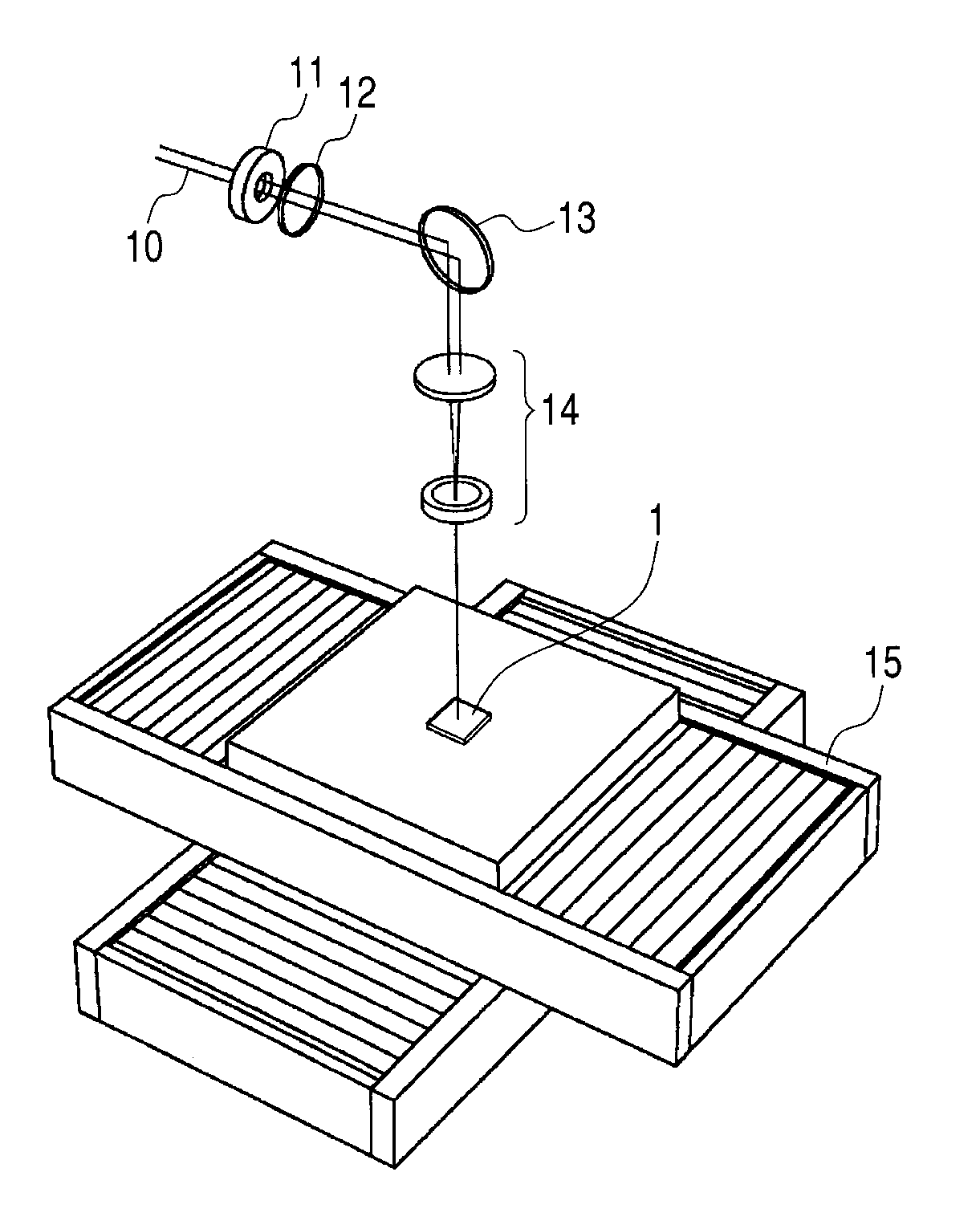
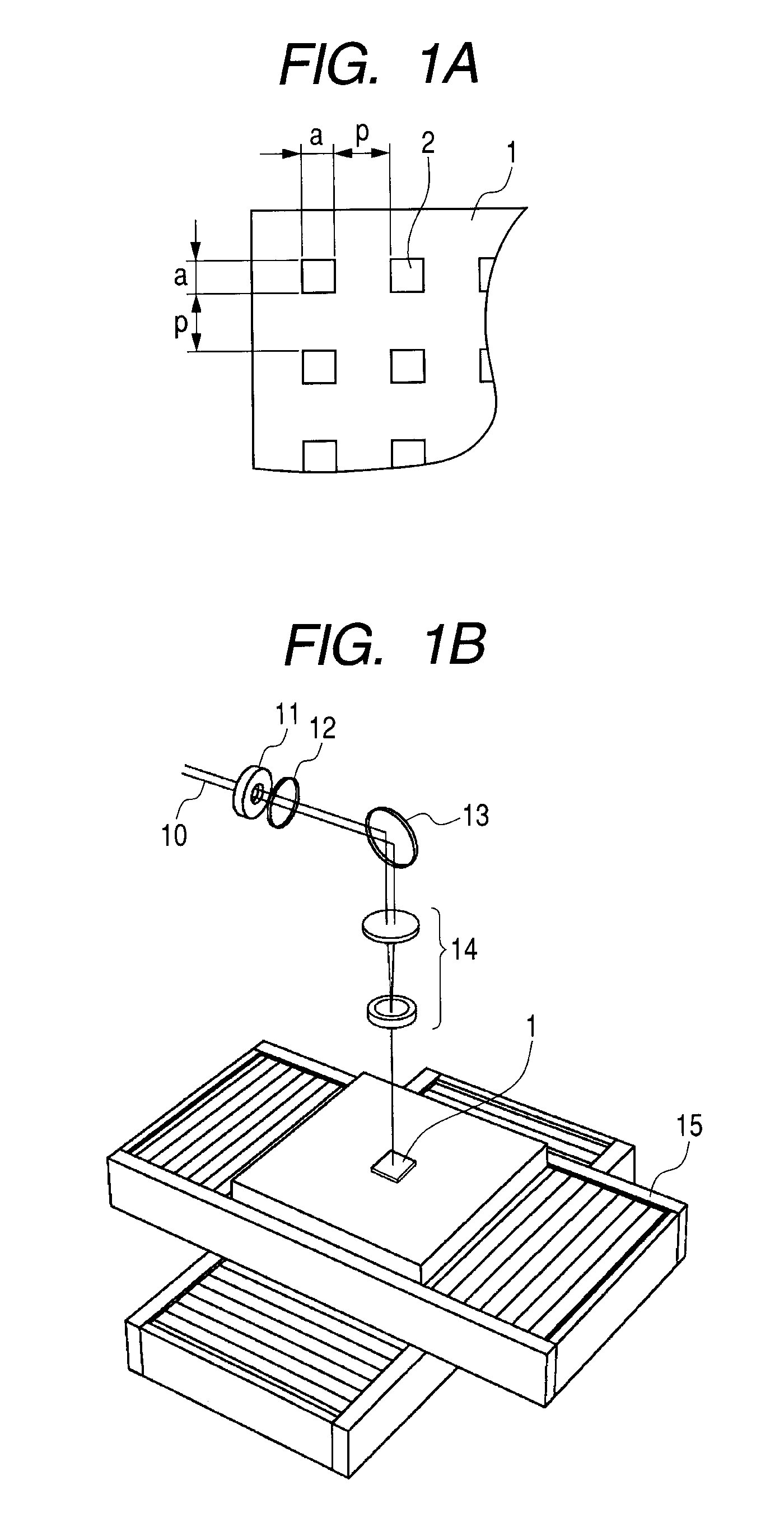
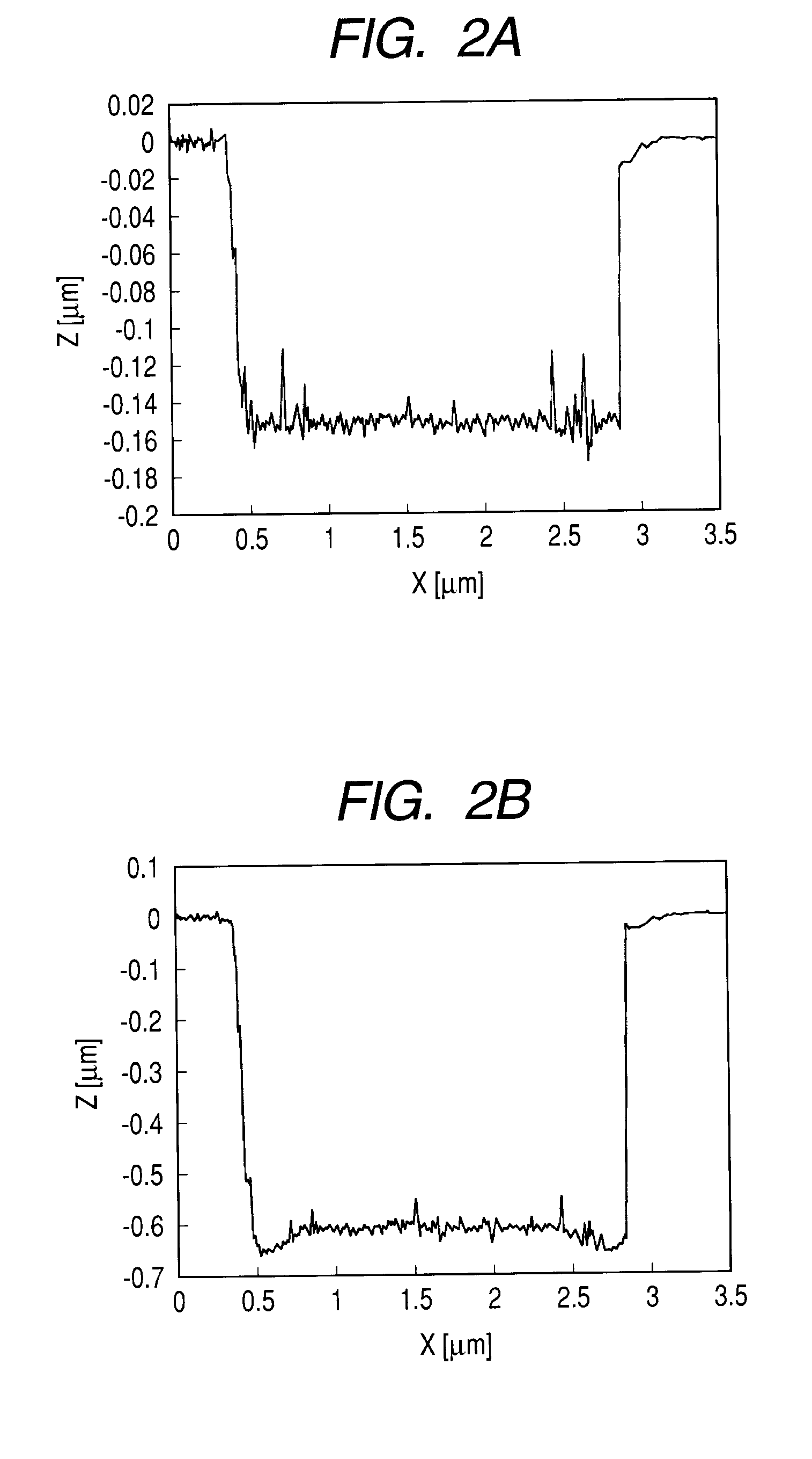
[0039]The processing method described in the above embodiment will be specifically described. As a basic shape formation step, a focused ion beam processing observation apparatus (hereinafter, referred to as FIB apparatus) was used to form a recess shaped pattern 2 shown in FIG. 1A on a workpiece 1. The workpiece 1 was a copper plate; and the recess shaped pattern 2 which was a square having one side length a of 2.5 μm and was smaller in difference in height than a desirable uneven shape was formed on the copper plate in a grid-like pattern at an interval p of 4.2 μm. In this step, the workpiece 1 was placed on a work stage of the FIB apparatus; a gallium ion beam was accelerated at an accelerating voltage of 40 kV; and a beam focused by an electron lens was applied to a workpiece surface via an aperture of 150 μm diameter. In this way, ablation processing of the workpiece surface was performed, and the processing was performed so that the depth of the pattern 2 became 0.15 μm. A cr...

example 2

[0045]FIG. 3 shows a processing apparatus used in a basic shape formation step and a shape growth step of the present example. A laser source used (not shown) was a titanium sapphire regenerative amplifier having a wavelength of 800 nm, a pulse width of 130 fs, and a repeating frequency of 1 kHz. A laser beam 31 having a wavelength of 800 nm, a pulse width of 130 fs, a repeating frequency of 1 kHz, a pulse energy of 1.2 mJ, and a beam diameter of 8 mm was obtained from the oscillation source. This laser beam was clipped to a beam diameter of 5 mm via an aperture 32; and divided into two beams by a beam splitter 36 via an attenuator 33, a shutter 34, and a mirror 35. One beam was passed through a shutter 37 and a mirror 38, condensed by a condenser lens 39, and applied to a surface of a workpiece 21 placed on a stage 45. The other beam was passed through an optical path length regulator 40, an ND filter 41, and a mirror 42; and was applied to the surface of the workpiece 21 by a cond...


PUM

PropertyMeasurementUnit
Timeaaaaaaaaaa
Timeaaaaaaaaaa
Widthaaaaaaaaaa

Abstract

In a processing method using laser light, light energy is effectively used and a time necessary for processing is shortened. The processing method includes a basic shape formation step of forming a recess pattern smaller in depth than a recess shape on a surface of a workpiece; and a shape growth step of irradiating the recess pattern with laser light which has a fluence such that the etching rate at a recess bottom surface of the recess pattern is larger than the etching rate on the workpiece surface and has a beam diameter larger than a width of the recess pattern so as to process the recess shape.

Description

TECHNICAL FIELD[0001]The present invention relates to microprocessing by laser processing, and, more particularly, relates to a processing method which processes a fine recess shape by using an ultrashort pulse laser.BACKGROUND ART[0002]It is known that general laser processing utilizes the effect by thermogenesis due to light absorption; however, in the case of using an ultrashort pulse laser, non-thermal processing is possible. Consequently, high quality processing can be performed without causing shape collapse or the like due to heat.[0003]However, in the case of performing microscopic and high quality processing by ultrashort pulse laser light, the irradiation energy is required to set to energy near to a processing threshold. In the case of giving large irradiation energy, an increase in processing dimension and damage of a peripheral portion of a machining region are incurred (see Masaki Hashida, Kengo Nagashima, Masayuki Fujita, Masahiro Tsukamoto, Masahito Kattou, and Yasuk...

Claims


Application Information

Patent Timeline
IPC IPC(8): B29C35/08B23K26/00B23K26/36
CPCB23K26/06B23K26/0635B23K26/421B23K26/385B23K26/36B23K26/0624B23K26/389B23K26/60
Inventor KOKUBO, SATOSHI
Owner CANON KK
Why Eureka
Try Eureka