Method and arrangement for detecting particles

Inactive Publication Date: 2011-08-18
VOLVO TECH +1
View PDF27 Cites 21 Cited by
  • Summary
  • Abstract
  • Description
  • Claims
  • Application Information

AI Technical Summary

Benefits of technology

[0012]The temperature control arrangement is arranged to lower the second temperature T2 at between 5-250° C., 5-150° C., or least 5° C., preferably at least 20° C., more preferably at least 30° C., lower than the first temperature T1. The sensor element can further comprise a first surface; the first

Problems solved by technology

In the field of vehicle exhaust gas cleaning, the industry faces the delicate balance of providing an adequate effect from the engine, which is demanded by the consumers, while not emitting to high quantities of harmful emissions, such as NOx, COx, hydrocarbons, particulates and the like.
These restrictions provide new challenges and opportunities to the vehicle industry.
In order to provide a proper exhaust gas cleaning system, the inventors have found that a key issue is to satisfy the need for proper detection and registration of harmful pollutants in the exhaust gas emitted from the vehicle during use, e.g. when driving a

Method used


Image

  • Method and arrangement for detecting particles
  • Method and arrangement for detecting particles
  • Method and arrangement for detecting particles

Examples


Embodiment Construction

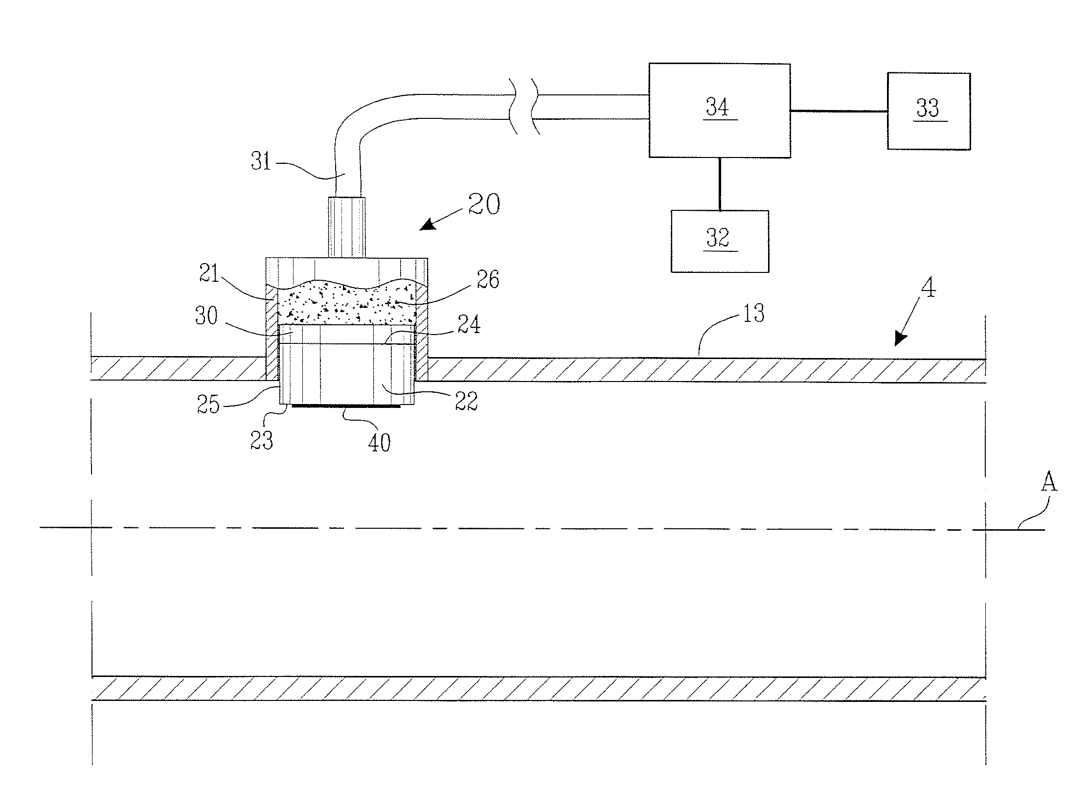
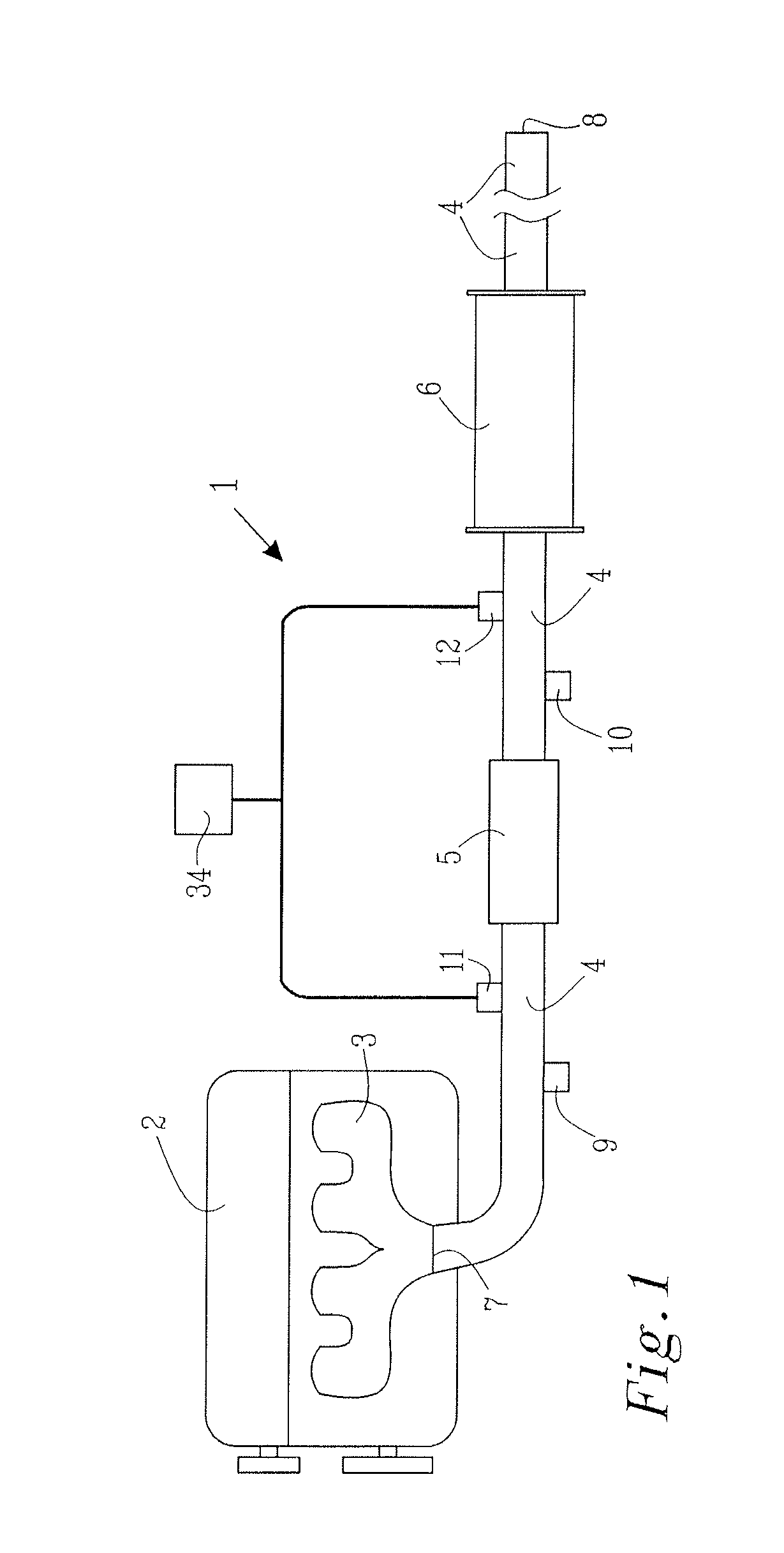
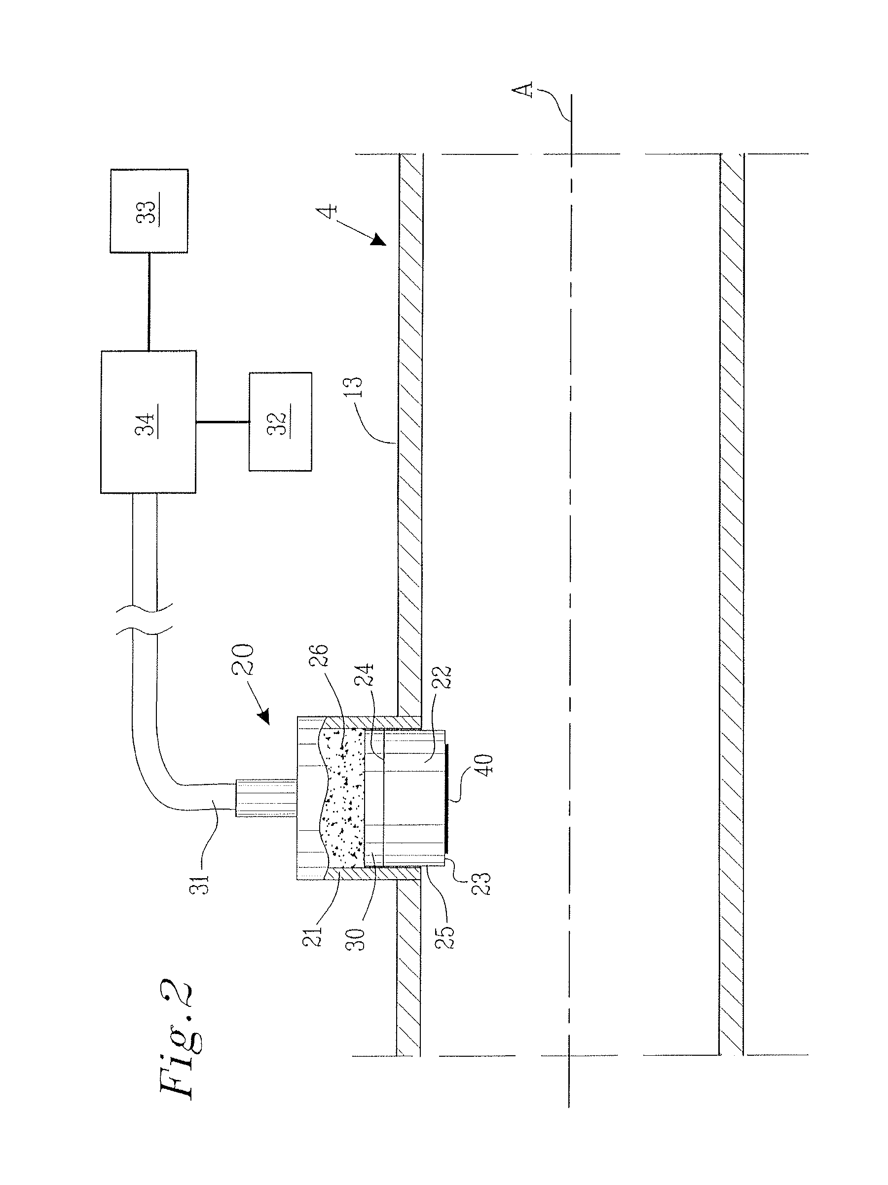
[0027]FIG. 1 show a schematic illustration of an exhaust gas system 1 connected to a diesel engine 2 at an engine exhaust gas port 3. Such an exhaust gas system 1 is preferably used in vehicles, such as trucks, boats, cars, trains, aircrafts or any other appropriate vehicle. The exhaust gas system 1 comprises, in the shown embodiment, of an exhaust gas pipeline 4, a diesel particle filter 5 and a muffler 6. The exhaust gas pipeline 4 comprises an inlet opening 7, through which the exhaust gas from the engine 2 enters the exhaust gas system 1, and an outlet opening 8, through which the exhaust gas exit the exhaust gas system 1 to the ambient air. A first and a second pressure sensor 9, 10 are arranged on respective side of the diesel particle filter 5. Additionally are a first and a second soot particle arrangement 11, 12, according to the present invention, arranged on respective side of the diesel particle filter 5. Although the present invention is herein described with reference ...


PUM


Abstract

The present invention relates to a method for detecting particles and a particle sensor arrangement. More specifically, the present invention relates to a method and arrangement for detecting particles in a gas flow, e.g. from a diesel combustion engine. The method comprises the steps of; forcing a particle build up on a sensor element of a particle sensor arrangement by regulating the sensor element to a second temperature; wherein the second temperature is lower than a first temperature, the first temperature being the gas flow temperature. Additionally is the particle build up detected at the sensor element by means of a detector. The present invention provides for an accurate method and arrangement to detect and thereby measure particles present in a gas flow, e.g. from a combustion engine.

Description

TECHNICAL FIELD[0001]The present invention relates to a method for detecting particles and a particle sensor arrangement. More specifically, the present invention relates to a method and arrangement for detecting particles in a gas flow.BACKGROUND OF THE INVENTION[0002]There is an increasing need for environmental friendly vehicles, engines, fuel and vehicle exhaust gas cleaning arrangements, all serving the purpose of striving towards a less harmful impact on the environment. In the field of vehicle exhaust gas cleaning, the industry faces the delicate balance of providing an adequate effect from the engine, which is demanded by the consumers, while not emitting to high quantities of harmful emissions, such as NOx, COx, hydrocarbons, particulates and the like. The demand to have a combustion engine and an exhaust gas cleaning system which strives towards zero emission are not only driven by the customers but also by legislators. Hence an increased awareness of the need for environm...

Claims


Application Information

Patent Timeline
IPC IPC(8): F01N3/021G01M15/10
CPCG01N27/4077G01N15/0255
Inventor VISSER, JACOBUS HENDRIKJOZSA MARDBERG, PETERLUTIC, DOINALLOYD SPETZ, ANITASANATI, MEHRI
Owner VOLVO TECH
Why Eureka
Try Eureka