Motor Grounding Seal

a technology of bearing isolator and sealing device, which is applied in the direction of engine components, dynamo-electric components, mechanical equipment, etc., can solve the problems of sealing wear and damage of electrical motors using variable frequency drives, difficult to obtain adequate maintenance of rotating equipment, and easy to fail. , to achieve the effect of preventing leakage of lubricant and entry

Inactive Publication Date: 2011-08-25
ORLOWSKI DAVID C +1
View PDF29 Cites 38 Cited by
  • Summary
  • Abstract
  • Description
  • Claims
  • Application Information

AI Technical Summary

Benefits of technology

[0011]An objective of the motor grounding seal is to provide an improvement to seals or bearing isolators to prevent leakage of lubricant and entry of contaminants by encompassing the stator within the rotor to create an axially directed interface at the radial extr

Problems solved by technology

Adequate maintenance of rotating equipment is difficult to obtain because of extreme equipment duty cycles, the lessening of service factors, design, and the lack of spare rotating equipment in most processing plants.
Lip seals or other contacting shaft seals can quickly wear to failure and are also known to permit excessive amounts of moisture and other contaminants to immigrate into the oil reservoir of the operating equipment before seal failure had exposed the interface between the rotor and the stator to the contaminants or lubricants at the radial extremity of the seal.
The problem of seal wear and damage as applied to electrical motors using variable frequency drives is compounded because of the very nature of the control of electricity connected to variable frequency drive (VFD) controlled motors.
There are many causes of bearing current including voltage pulse overshoot in the

Method used


Image

  • Motor Grounding Seal
  • Motor Grounding Seal
  • Motor Grounding Seal

Examples


Embodiment Construction

—ELEMENT LISTING

[0027]

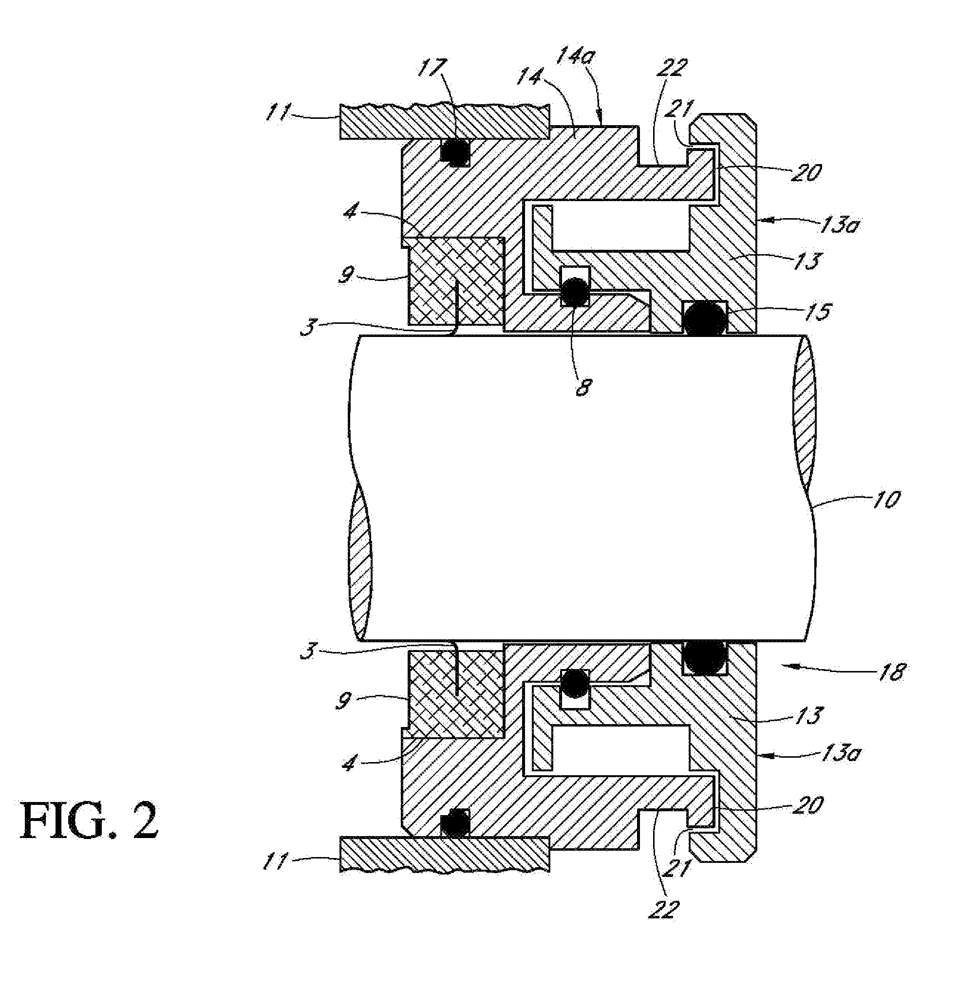
DescriptionElement No.Drive bearing 2Conductive brushes 3Receptor groove 4Brush ring 5Metallic insert with solid conductor ring 6Conductive insert ring 7O-ring 8Solid conductive ring 9Rotatable shaft10Housing11Rotatable shaft center12Rotor13Rotor surface13aStator14Stator surface14aO-ring15Brush ring frame16O-ring17Motor ground seal assembly18Radial projection19First radial Interface gap20Second radial interface gap21Stator groove22

DETAILED DESCRIPTION

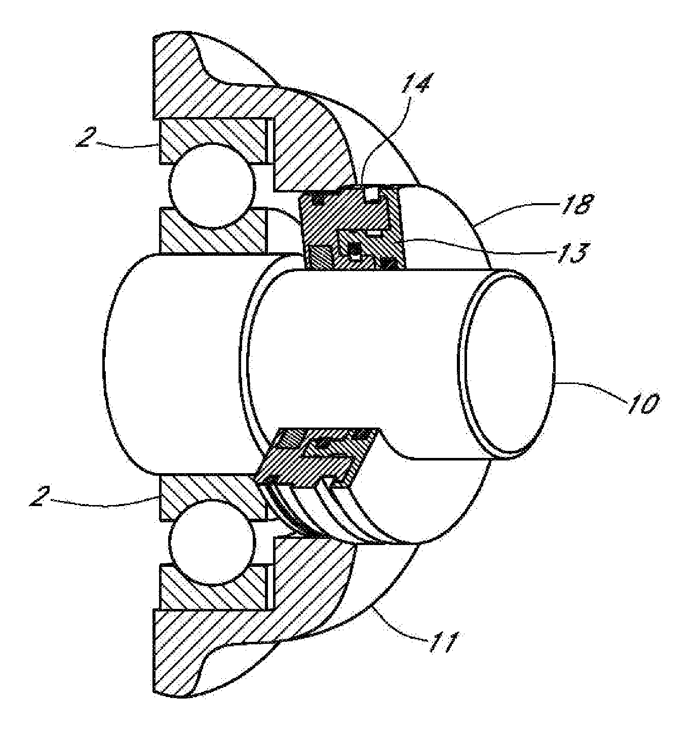
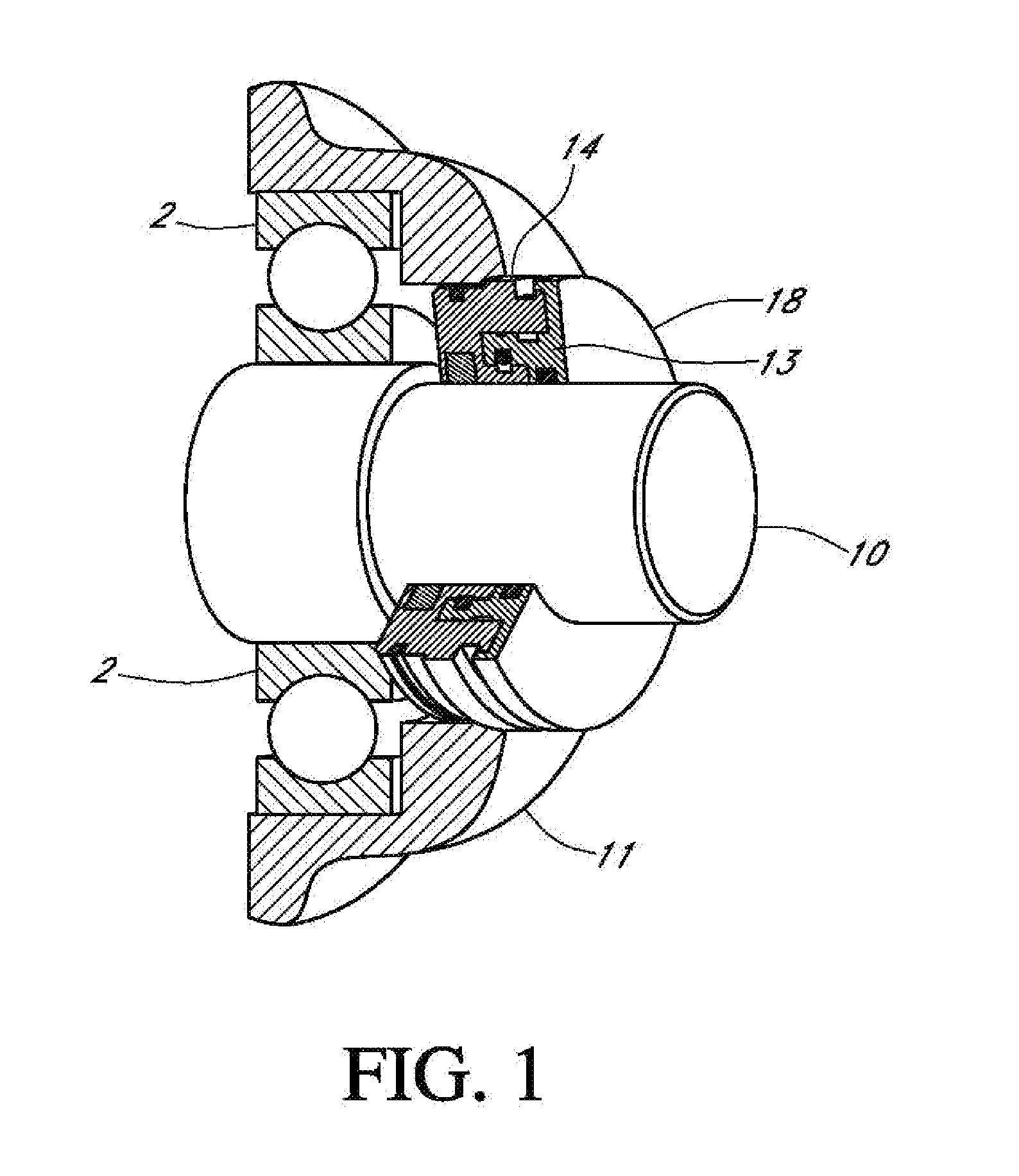
[0028]FIG. 1 illustrates a perspective view of the motor ground seal assembly 18 applied to a rotatable shaft 10 of an electrical motor (not shown)having a variable frequency drive (VFD). The motor grounding seal™ assembly 18 shown in FIG. 1 may be mounted to rotatable shaft 10 on either one or both sides of the motor housing assembly 11. The motor grounding seal™ assembly 18 may be flange-mounted, press-fit, or attached by other means to a housing 11. The motor ground seal assembly 18 will also function with a rot...


PUM


Abstract

A shaft seal assembly is disclosed having a stator including a main body and axial and radial projections therefrom. The rotor may be radially extended to encompass the axial and radial projections from said stator. A passageway formed between the radial projection of stator and rotor results in an axial passageway having its opening facing rearwardly from the rotor and away from the source of impinging coolant and/or contaminant. A concentric circumferential receptor groove in the stator facing the housing allows insertion of a conductive insert for transmission of electrostatic charge away from the shaft through the shaft seal assembly to the housing and ground. The receptor groove is opposite the axial passageway and provides for both a substantially lower contaminant environment and improved engagement with the conductive insert.

Description

CROSS-REFERENCE TO RELATED APPLICATIONS[0001]The present application is a continuation-in-part and claims priority from U.S. patent application Ser. No. 12 / 401,331 filed on Mar. 10, 2009 which application was a continuation of and claimed priority from U.S. patent application Ser. No. 11 / 378,208 filed on Mar. 17, 2006, which claimed the benefit of U.S. provisional App. No. 60 / 693,548, filed Jun. 25, 2005, all of which are incorporated herein in their entireties.FIELD OF THE INVENTION[0002]The present invention relates to an improved bearing isolator sealing device, and more particularly, to a bearing isolator for directing electrostatic charge to ground while retaining lubrication solution and repelling contamination such as water, dust, dirt, sand and paper stock from the bearing environment and away from the shaft grounding ring, within the bearing cavity of a hub assembly such as an electrical motor bearing for engagement with a rotatable shaft.STATEMENT REGARDING FEDERALLY SPONS...

Claims


Application Information

Patent Timeline
IPC IPC(8): H02K5/124
CPCF16J15/4478F16C33/80H02K11/0089H02K5/10H02K11/40
Inventor ORLOWSKI, DAVID C.COE, THOMAS D.
Owner ORLOWSKI DAVID C
Why Eureka
Try Eureka