
Energy storage system

a technology of energy storage and energy storage device, which is applied in the direction of cell components, sustainable manufacturing/processing, and final product manufacturing, etc., can solve the problems of insufficient size of conventional energy storage devices, and achieve the effect of improving step coverage, avoiding pronounced topography, and simple process

Inactive Publication Date: 2011-11-10
NXP BV +1
View PDF1 Cites 12 Cited by
  • Summary
  • Abstract
  • Description
  • Claims
  • Application Information

AI Technical Summary

Benefits of technology

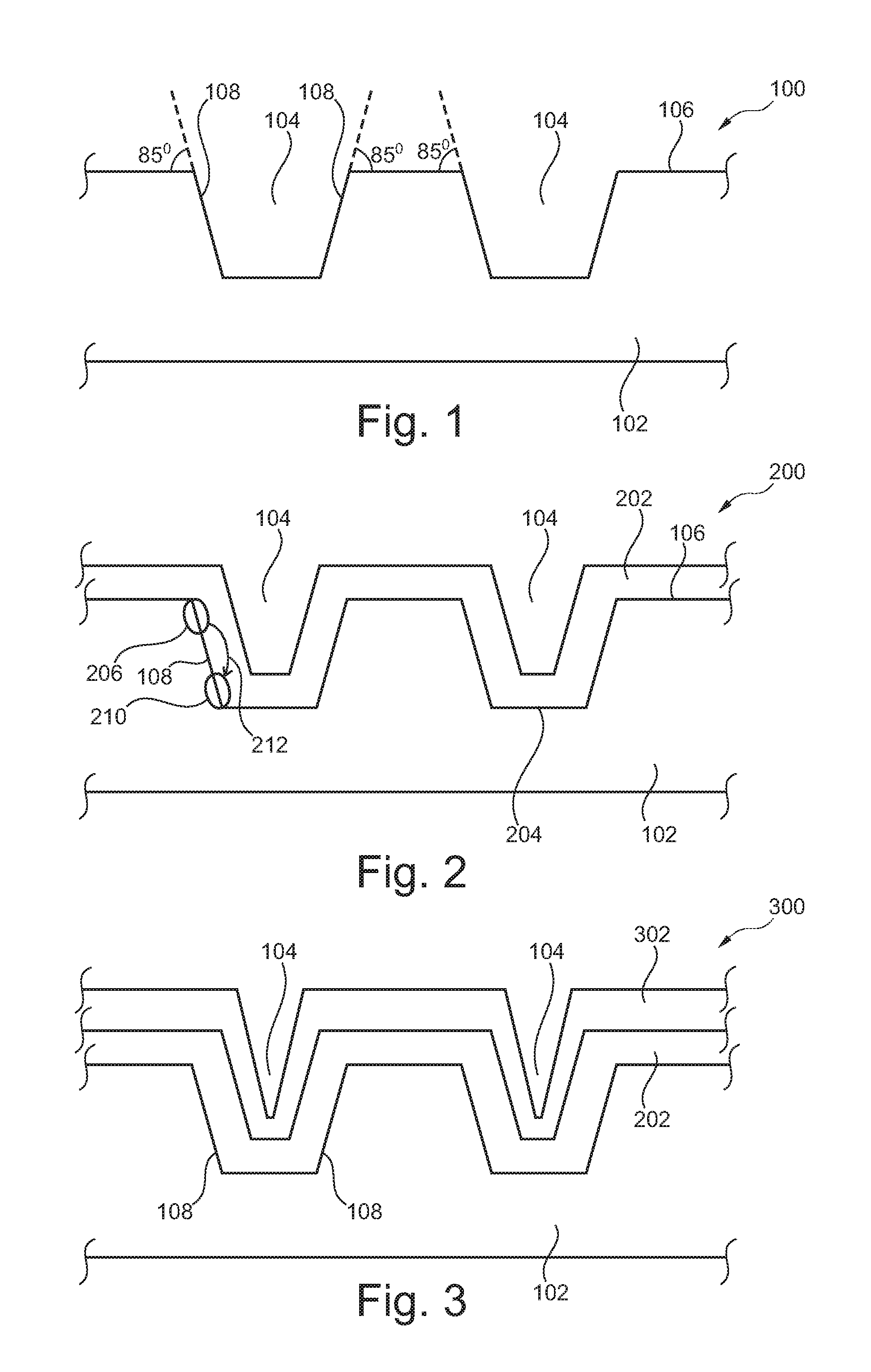
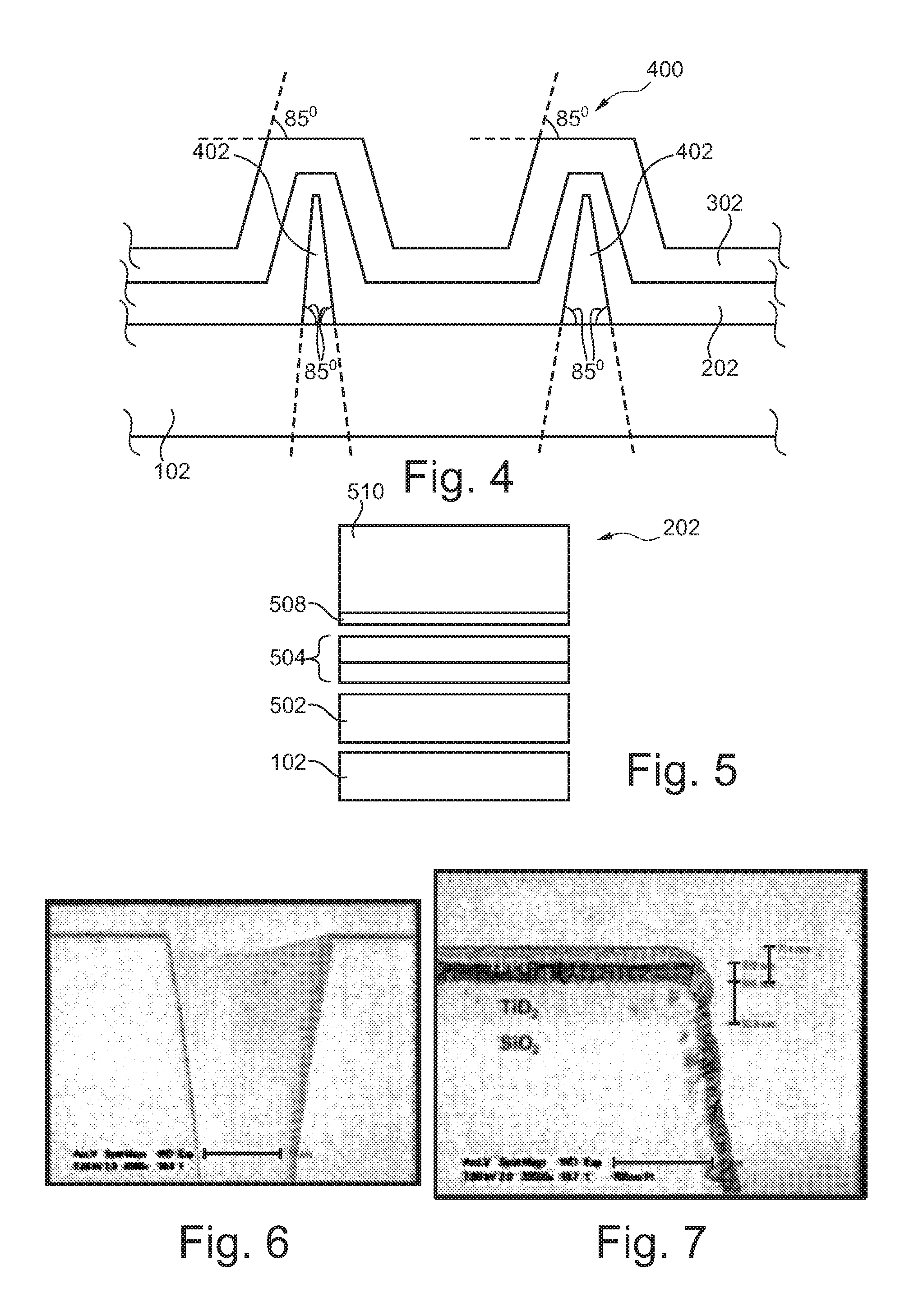
[0025]According to an exemplary embodiment of the invention, an energy storage device such as a battery is provided which can be monolithically integrated in a substrate and which has a large active surface on which energy can be stored. This can be made possible by providing the steric structure as a three-dimensional profile on or in the substrate and by depositing subsequently the layers contributing to the battery function on this steric structure. Hence, a three-dimensional geometry may be achieved with a significantly enlarged active area thereby significantly improving the energy storage performance of the system. The present inventors have surprisingly recognized that the provision of an acute angle of more than 80° can be made possible particularly by implementing physical vapour deposition and forming a layer sequence of deposited layers that have a significantly improved conformality on a sterically patterned substrate. This may improve the battery characteristic and may simultaneously result in reliable devices which are not prone to failure even under harsh conditions.
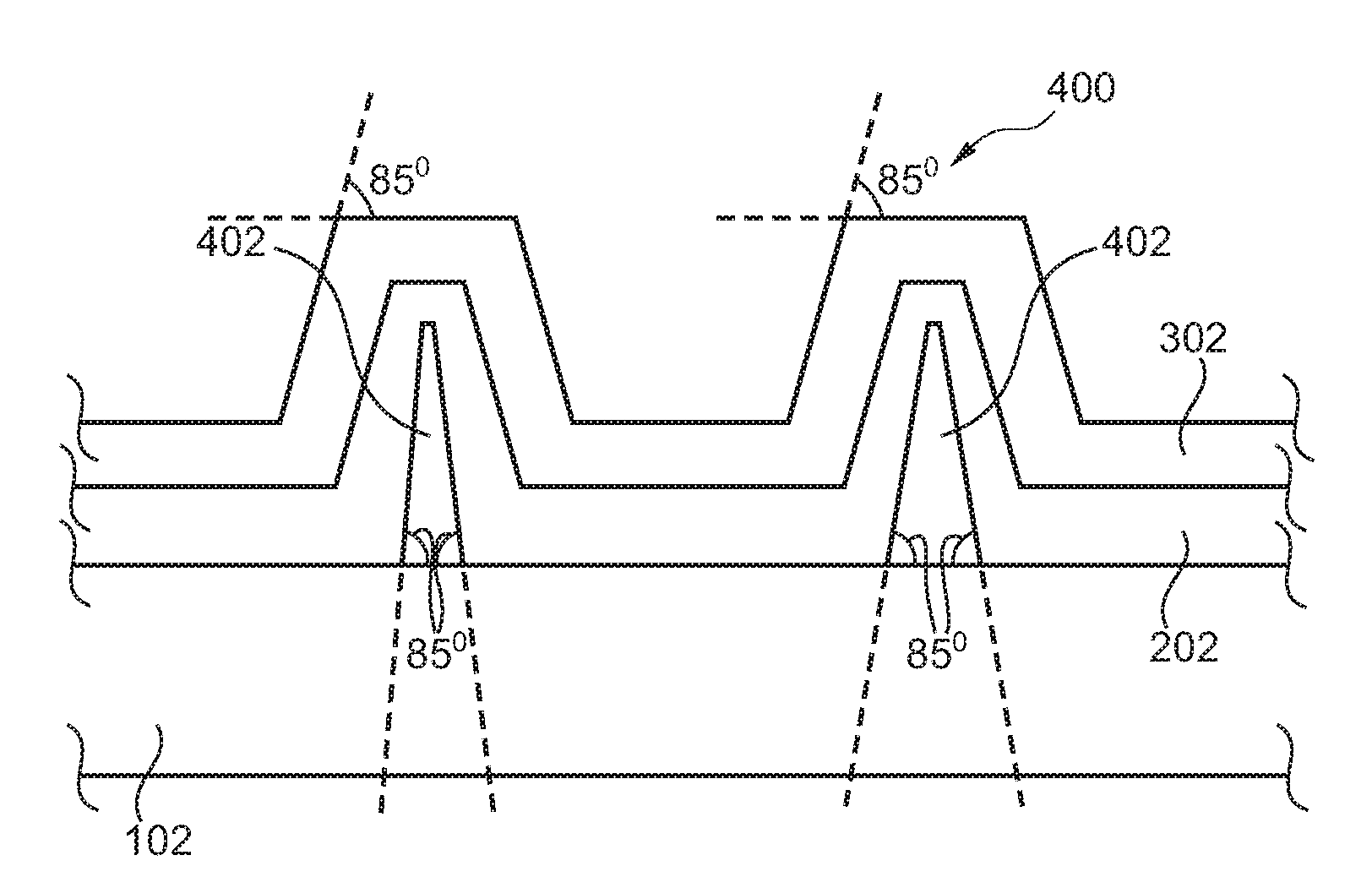
[0031]The steric structure may additionally or alternatively comprise at least one protrusion formed on the substrate. Such a protrusion or pillar may be a structure which extends from the main surface of the substrate and is formed for instance by layer deposition and etching. Alternatively, such protrusions may be formed by formed structures such as nanotubes or nanowires. Such protrusions have a similar effect as the trenches, namely to increase the active area of the energy storage. Examples for protrusion geometries are a rectangle, a trapezoid, a triangle, etc. Such a protrusion may have an aspect ratio (that is a ratio between vertical length and diameter of the protrusion) of larger than two, particularly of larger than five.
[0038]The electronic apparatus can be particularly applied to all applications in which an energy supply of a remotely arranged or autarkic operating functional member is required. For example, in a distributed sensor system in an environment which cannot be accessed easily from an exterior position, a long life-time battery with small dimensions may be of particularly advantage. Other examples for electronic apparatuses according to exemplary embodiments are long life-time autonomous applications (for instance a filling level sensor), a lighting control unit (such as a wireless button), a presence and motion detection device (for instance for security applications in private buildings), a building control unit (for instance controlling the energy supply within a building), an autonomous light source (for example for illuminating roads or public places), a green house sensor platform, a wireless add-on sensor (for instance a wireless sensor detecting a temperature) or a medical implantable device (which may be implanted in a physiological object such as a human being to perform specific sensor functions, for instance glucose level detection functions, within the human body).
[0041]The method may comprise forming the current collector stack and / or the electric storage stack by PVD. Hence, these key components for the proper functioning of the electric energy supply unit may be manufactured with a very simple process.
[0042]The method may comprise covering the steric structure with the current collector stack by substrate biased sputter deposition. Substrate biased sputter deposition may involve firstly covering upper portions of trenches and horizontal surface portions of a patterned substrate with material and subsequently rearranging material from these portions to the side wall portion of the trench to obtain a homogeneous thickness of the deposited material. During resputtering, material from the bottom of the trench may be resputtered on the side wall in order to improve step coverage whereas material near the top of the trench is removed and / or redistributed over the substrate and / or the top part of the side wall of the trenches. By taking this measure, a pronounced topography may be avoided and a high reliability may be ensured. The sputter redeposition (resulting from biased sputtering) may occur simultaneously for both top surfaces and side walls.
[0043]The method may comprise manufacturing the energy storage device as a full all-solid state device by physical vapour deposition. Such a device may be manufactured in a compact way without any non-solid state (for instance liquid) components, so that the system can be made robust against damage.

Problems solved by technology

However, conventional energy storage devices may be still too large in size.

Method used


Image

  • Energy storage system
  • Energy storage system
  • Energy storage system

Examples


Embodiment Construction

[0059]The illustration in the drawing is schematical. In different drawings, similar or identical elements are provided with the same reference signs.

[0060]Before describing exemplary embodiments in further detail, some basic recognitions will be summarized based on which exemplary embodiments of the invention have been developed. Exemplary embodiments relate to the sputter deposition of multilayers in 3D, for example for all solid state batteries.

[0061]The capacity of multi-layer stack capacitors and batteries can be increased significantly by growing these devices in / on three-dimensional (3D) substrates. Examples of 3D configurations are pores, trenches, pillars, honeycombs, etc. The capacity increase depends on the surface enhancement, which is related to the aspect ratio and the number of 3D units.

[0062]Conventionally, deposition of multi-layer stacks in 3D can be achieved by Atomic Layer Deposition (ALD) and / or Chemical Vapour Deposition (CVD). With ALD it is possible to deposi...


PUM


Abstract

An energy storage device (300), the device (300) comprising a substrate (102), a steric structure (104) formed on and / or in a main surface (106) of the substrate (102), a current collector stack (202) formed on the steric structure (104), and an electric storage stack (302) formed on the current collector stack (202), wherein side walls (108) of the steric structure (104) and the main surface (106) of the substrate (102) enclose an acute angle of more than 80 degrees.

Description

FIELD OF THE INVENTION[0001]The invention relates to an energy storage device and / or an electrochemical device.[0002]Furthermore, the invention relates to an electronic apparatus.[0003]Moreover, the invention relates to a method of manufacturing an energy storage device.BACKGROUND OF THE INVENTION[0004]In electronics, a battery comprises an electrochemical cell which stores chemical energy which can be converted into electrical energy. The battery has become a common power source for many household and industrial applications.[0005]WO 2005 / 027245 discloses an electrochemical energy source comprising at least one assembly of a first electrode, a second electrode, and an intermediate solid-state electrolyte separating said first electrode and said second electrode. The disclosure also relates to an electronic module provided with such an electrochemical energy source. The disclosure further relates to an electronic device provided with such an electrochemical energy source. Moreover, ...

Claims


Application Information

Patent Timeline
IPC IPC(8): H01L27/06H01L21/02H01M4/04H01M4/1391H01M4/1395H01M4/525H01M10/0525H01M10/0562H01M10/058
CPCH01M4/0423H01M4/0426H01M4/1391H01M4/1395H01M4/382Y02E60/122H01M4/70H01M6/40H01M10/0525H01M10/0562H01M10/058H01M4/525Y02E60/10Y02P70/50
Inventor BESLING, WILLEM FREDERIK ADRIANUSNIESSEN, ROGIER ADRIANUS HENRICAKLOOTWIJK, JOHAN HENDRIKVERHAEGH, NYNKENOTTEN, PETRUS HENRICUS LAURENTIUSMULDER, MARCEL
Owner NXP BV
Learn More