Optical sensor of bio-molecules using thin-film interferometer

an optical sensor and biomolecule technology, applied in the direction of interferometric spectrometry, instruments, optical elements, etc., can solve the problems of reducing coupling efficiency, poor alignment, and difficulty in maintaining the same exact air gap size for different pairs of sensors and instruments

Active Publication Date: 2011-12-15
ACCESS MEDICAL SYSTEMS LTD
View PDF4 Cites 11 Cited by
  • Summary
  • Abstract
  • Description
  • Claims
  • Application Information

AI Technical Summary

Benefits of technology

[0012]The present invention is also directed to an assembly comprising: (a) a waveguide; (b) a monolithic substrate having a coupling side and a sensing side, the coupling side is optically coupled to the waveguide; and (d) a thin-film layer directly bonded to the sensing side of the monolithic substrate. The waveguide transports a light signal from a light source to the assembly, and the waveguide transports reflected light signals from the assembly to a detector. The thin film layer comprises a transparent material, a first reflecting surface comprising a layer of analyte binding molecules, and a second reflecting surface between the thin film layer and the monolithic substrate. The refractive index of the monolithic substrate is higher than the refractive index of the transparent material of the thin-film layer; and the refractive index of the coupling medium is greater than 1.3, preferreably in between refractive indexes of the waveguide and the monolithic substrate. A spectral interference between light reflected into the waveguide from said first and said second reflecting surfaces varies as analyte molecules in the sample bind to the analyte binding molecules. In one embodiment, the assembly further comprises a conpling medium between the waveguide and the monolithic substrate, wherein the refractive index of the coupling medium is greater than 1.3.

Problems solved by technology

One drawback is the reduction in coupling efficiency.
Another problem is poor alignment.
Practically, it is difficult to maintain the same exact air gap size for different pairs of sensors and instruments.
In addition, air-fiber interface tends to causing higher reflection back to the spectrometer that can decrease the measurement signal-to-noise ratio.

Method used


Image

  • Optical sensor of bio-molecules using thin-film interferometer
  • Optical sensor of bio-molecules using thin-film interferometer
  • Optical sensor of bio-molecules using thin-film interferometer

Examples


example 1

Preparation of Streptavidin Probes

[0075]A glass rod (a monolithic substrate), 1 mm diameter and 2 cm in length, had both coupling end and sensing end polished. The sensing end was first coated with a SiO2 coating layer (a thin-film layer) with a thickness of 650 nm using a physical vapor deposition technology, and then deposited with aminopropylsilane (APS) using a chemical vapor deposition process (Yield Engineering Systems, 1224P) following manufacturer's protocol. APS is deposited to enable protein immobilization. APS adsorbs protein to the surface of the probe by a combination of hydrophobic and ionic interaction. Protein can also be coupled to the amino group of APS by covalent coupling using a crosslinking reagent. APS is only a monolayer, about 7 nm thick.

[0076]The probe (the glass rod coated with SiO2 and APS) was then inserted into the center bores of the molded plastic hubs, as shown in FIG. 3. The probe was then locked to the hub by either adhesive or a locking mechanism....

example 2

Detection of Protein A Binding to Human IgG

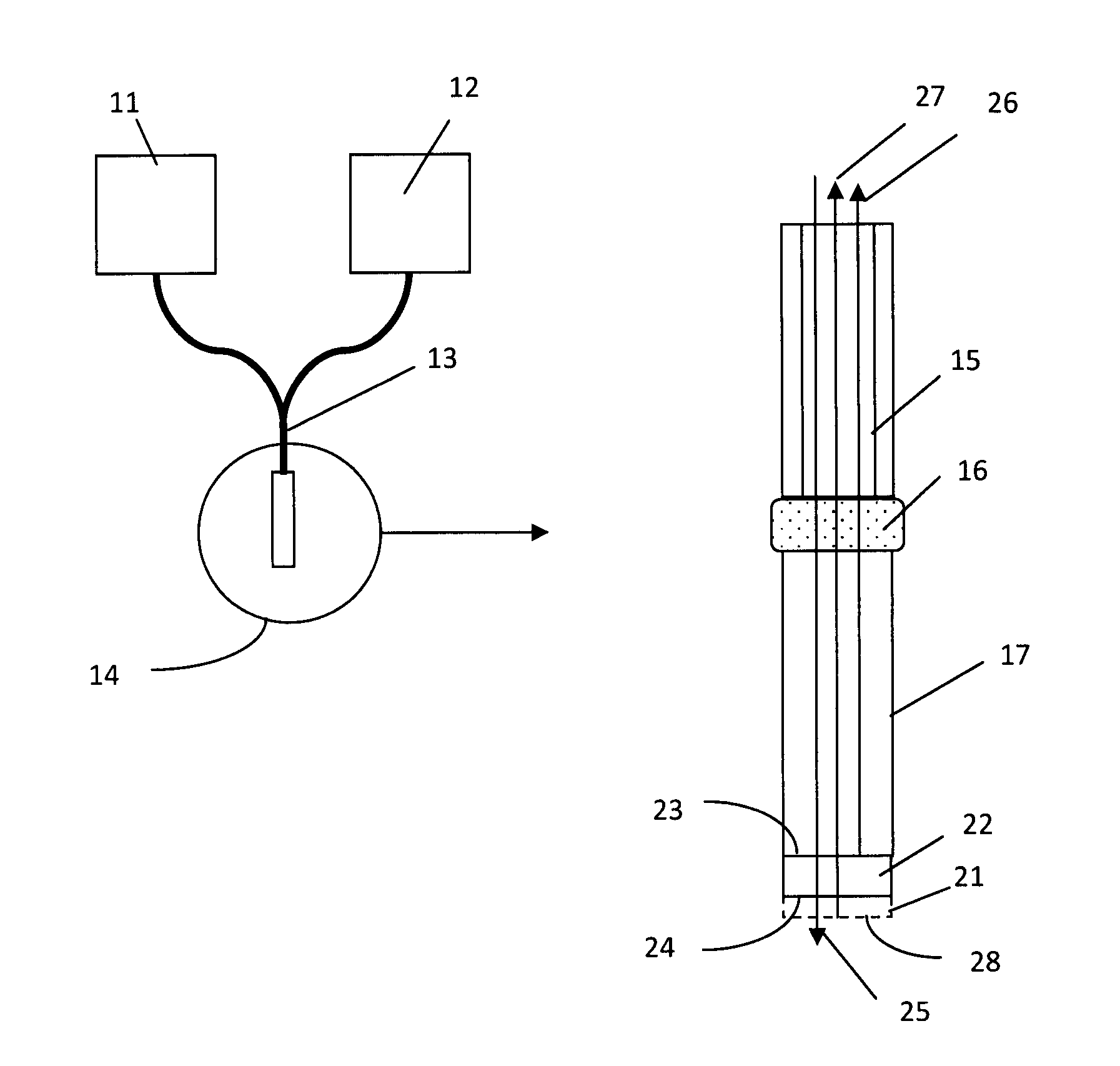
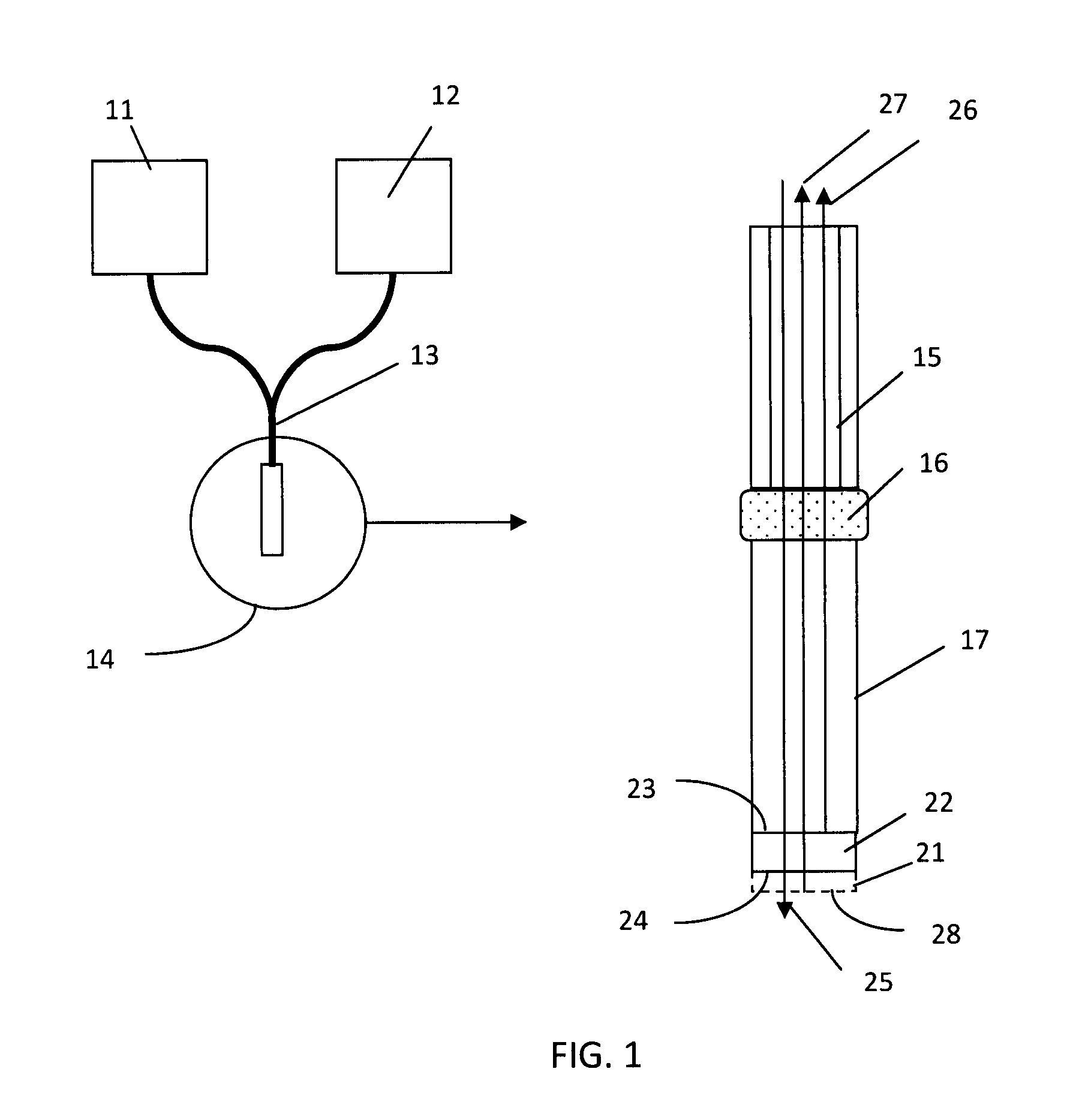
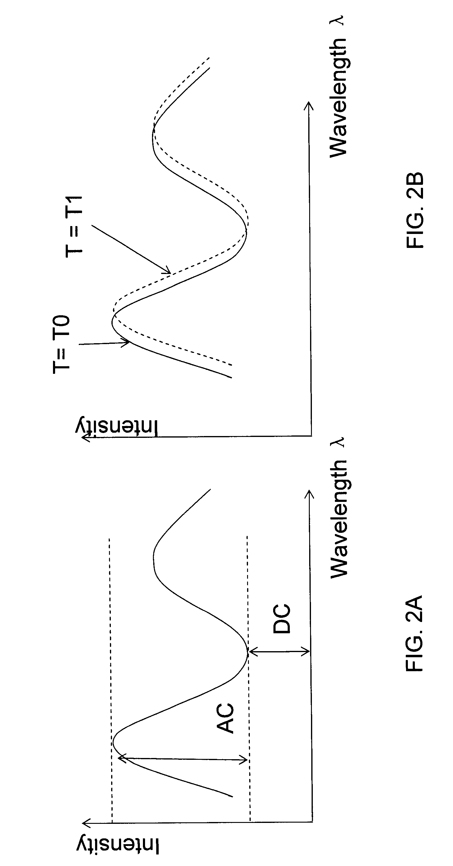
[0078]As shown in FIG. 3, each probe was first connected to waveguides in a ferrule. The waveguides connect to a halogen light source and a spectrometer so the light will be transported to the probe's sensing surface and reflected light will be transported to the spectrometer for measurement. Multiple of such systems can be set up to achieve parallel detection. The spectrometers measure the reflected light from the sensing ends of the probes and output spectral interference patterns in a real-time function of wavelengths and light intensity at each wavelength. A typical interference pattern is shown in FIG. 13. A phase change in the form of left shift of the peaks and valleys represents a reduction of the thin-film thickness (disassociation of molecules on the sensing surface); and a right shift means an increase of the thin-film thickness (association of molecules on the sensing surface). By converting the interference pattern to a digital...


PUM

PropertyMeasurementUnit
refractive indexaaaaaaaaaa
diameter aspect ratioaaaaaaaaaa
refractive indexaaaaaaaaaa

Abstract

The present invention is directed to an assembly for use in detecting an analyte in a sample based on thin-film spectral interference. The assembly comprises a waveguide, a monolithic substrate optically coupled to the waveguide, and a thin-film layer directly bonded to the sensing side of the monolithic substrate. The refractive index of the monolithic substrate is higher than the refractive index of the transparent material of the thin-film layer. A spectral interference between the light reflected into the waveguide from a first reflecting surface and a second reflecting surface varies as analyte molecules in a sample bind to the analyte binding molecules coated on the thin-film layer.

Description

[0001]This application is a continuation of PCT / US2010 / 024801, filed Feb. 19, 2010; which claims the priority of U.S. Provisional Application Nos. 61 / 208,215, filed Feb. 20, 2009; and 61 / 279,077, filed Oct. 15, 2009. The contents of the above-identified applications are incorporated herein by reference in their entirety.TECHNICAL FIELD[0002]This invention relates to an apparatus that improves detecting the presence, amount, or rate of binding of one or more analytes in a sample, and in particular an apparatus utilizing thin-film interferometer technology.BACKGROUND OF THE INVENTION[0003]Diagnostic tests based on a binding event between members of an analyte-anti-analyte binding pair are widely used in medical, veterinary, agricultural and research applications. Typically, such methods are employed to detect the presence or amount or an analyte in a sample, and / or the rate of binding of the analyte to the anti-analyte. Typical analyte-anti-analyte pairs include complementary strands ...

Claims


Application Information

Patent Timeline
Patent Type & Authority Applications(United States)
IPC IPC(8): G01N33/53
CPCG01N21/45G02B6/262G01N21/7703G01J3/45G01N21/648G01N21/8507G01N2021/7779G01N2201/062G01N2201/08G02B6/30
Inventor TAN, HONGTAN, YUSHANCAO, ERHUAXIA, MINZUK, ROBERT F.
Owner ACCESS MEDICAL SYSTEMS LTD
Why Eureka
Try Eureka