Cryogenic liquid storage tank

Inactive Publication Date: 2011-12-29
IGLO CONTRACTORS
View PDF17 Cites 12 Cited by
  • Summary
  • Abstract
  • Description
  • Claims
  • Application Information

AI Technical Summary

Benefits of technology

[0041]An advantage of the invention, by integrating the metal barrier in the sandwich structure comprising an inner and an outer concrete layer of the inner leaf, is the fact that the thickness of the metal barrier may be reduced compared to what is used in the prior art. The significantly reduced thickness of the metal barrier allows selecting a higher quality metal membrane, e.g. a highly ductile, stainless steel which may follow and adapt to thermal contraction when the tank is cooled during filling of LNG.
[0042]Another advantage of the invention is that a continuous transition is obtained between the base sandwich structure and the wall sandwich structure, from a structural point of view forms no structural weakness. This is an advantage from a seismic safety point of view. It is also an advantage from a construction operational point of view because reinforcement may be continued from the bottom concrete layer to the wall layer both for the outer leaf and for the inner leaf without undesired termination of the reinforcement.
[0043]Further, it is a significant advantage from a leakage prevention point of view due to the formation of a continuous metal membrane and its undisturbed position between the concrete layers in the transition between floor and wall. It is a general problem with large concrete cryogenic tanks constructed according to the background art that they may be leak tested before being cooled down to cryogenic temperatures. However, with the background art tanks one may have no guarantee for fluid tightness after cryogenic cooling. The present invention, which provides a continuous metal membrane within the concrete layers of the inner leaf, may be tested for fluid tightness before being cooled from ambient temperature, and will have no relative movements between the metal membrane encapsulated and the encapsulating concrete layers of the inner leaf.
[0044]An advantage is also found in an embodiment with the combination of a continuous transition combined with the convex embodiment having an outwardly inclined lower side wall, the reduced angle for such a floor to wall transition the structural stability, particularly horizontal force transfer both during thermal contraction or expansion, is further enhanced as compared to the vertical cylindrical wall structure.
[0045]An advantage of the convex embodiment of the invention is that the surface area of the tank according to the invention is significantly reduced compared to the surface area of a cylindrical tank of the same volume. A convex tank may have a larger diameter at the middle of the side wall than at the bottom, and it may also have a reduced top diameter compared both to the middle and bottom of the side wall. The surface area of the tank according to the invention, given the area defined by the relative diameter of the base and the shape and relative diameter of the roof, approaches the surface area of a sphere, which is the smallest possible surface area for a given volume. The result of approaching the smaller surface area of a corresponding sphere reduces the heat influx to the cryogenic tank and thus the boil-off, which is proportional to the heat influx.
[0046]Another advantage of that embodiment is that, from an economical point of view, one may obtain a larger stored volume for the same mass of construction material.

Problems solved by technology

However, the thick metal plates are expensive to produce and to shape and take time to join together, making this form of construction expensive.
One limiting factor in the construction of such tanks is the size of the dome.
A main limiting factor is the size of the dome and the generally horizontal forces induced on the top of the sidewall by the weight of the dome.
Another limiting factor is the internal bending moment induced in a widely spanning dome.
The steel sections of the dome may only be lifted into place when weather conditions are calm, and thus construction schedules are easily disrupted.

Method used


Image

  • Cryogenic liquid storage tank
  • Cryogenic liquid storage tank
  • Cryogenic liquid storage tank

Examples


Embodiment Construction

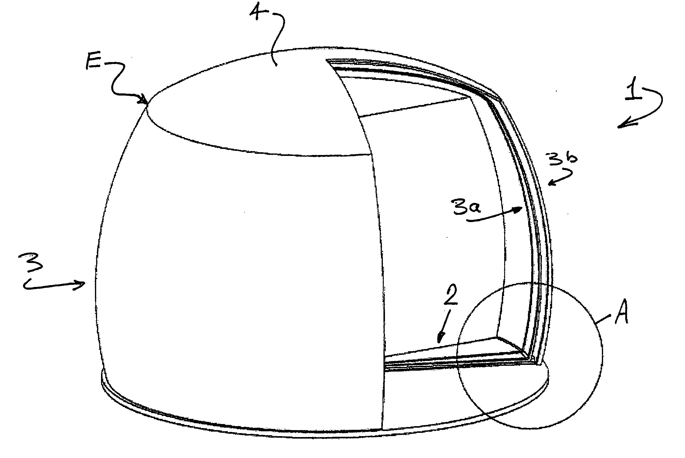
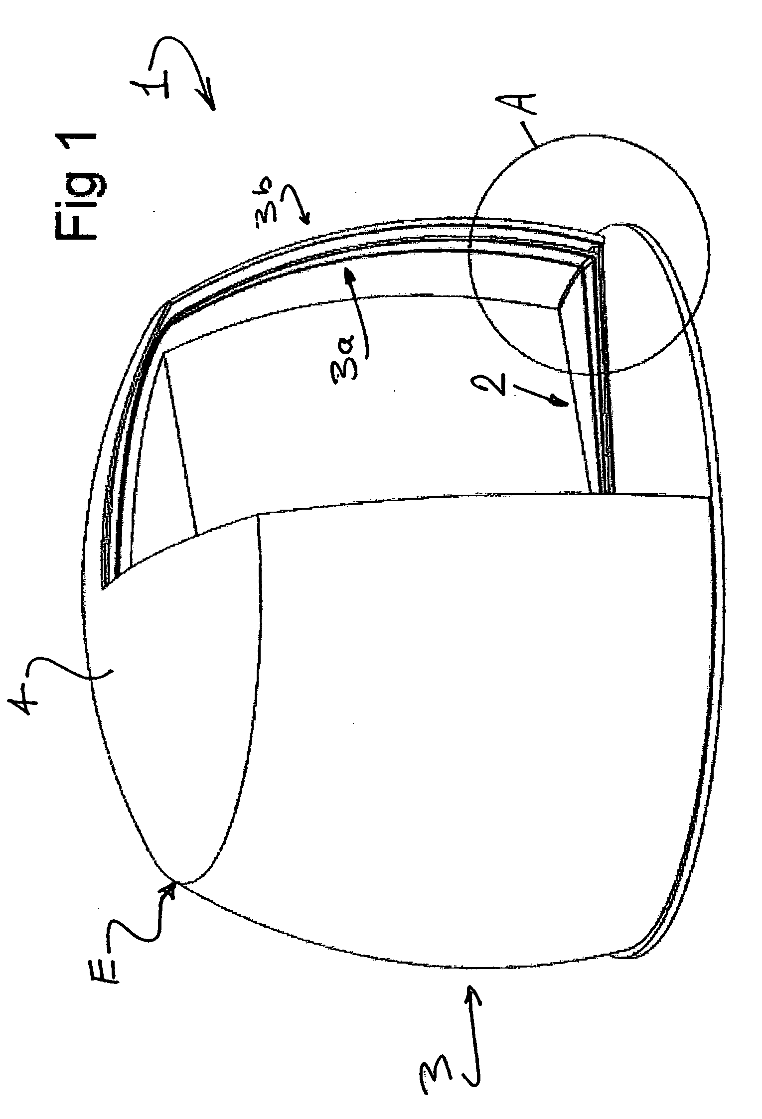
[0065]Referring now to the drawings, FIGS. 1 to 3 illustrate an embodiment of a storage tank 1 according to the present invention. The storage tank 1 comprises an inner tank part and an outer tank part here called inner and outer leaves 3a and 3b. The tank wall 3 is formed on a circular base 2. A dome 4 closes the top of the tank 1.

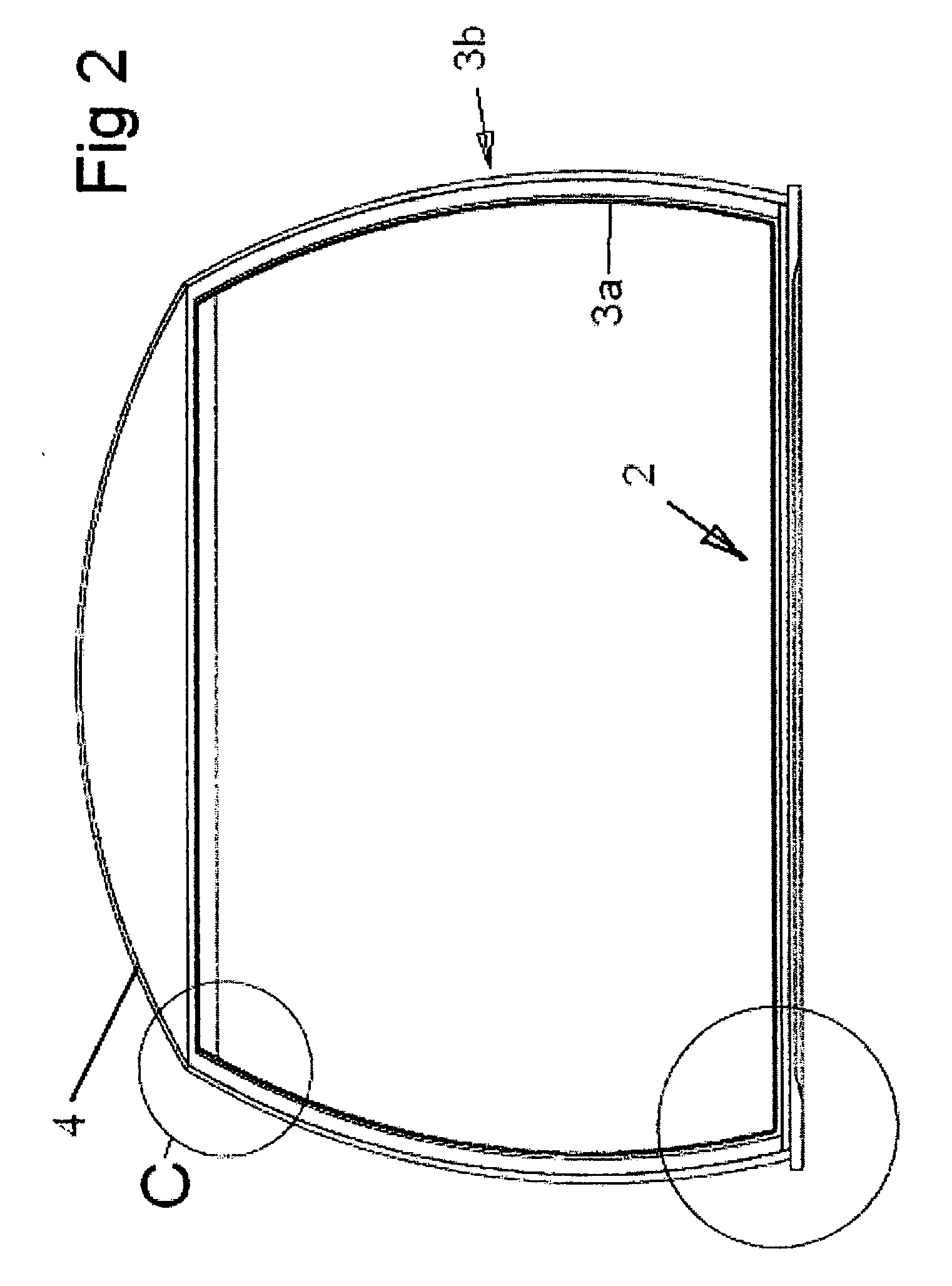
[0066]As can be clearly seen from FIGS. 1 and 2, the sidewall 3 of the tank is generally circular in plan shape, but differs in an embodiment of the invention from the conventional tank in that the sidewall is not straight in vertical section, but it is curved so as to present a convex face to the outside of the tank. At the lower edge of the sidewall, the sidewall is inclined outwardly from the base. The sidewall 3 curves inwardly from the base to its upper edge, resulting in an outwardly convex shape to the tank.

[0067]In the illustrated embodiment, the base 2 comprises a firm footing, of for example concrete, in the form of a baseplate 5. The outer leaf...


PUM

PropertyMeasurementUnit
Metallic bondaaaaaaaaaa
Contraction enthalpyaaaaaaaaaa
Stress optical coefficientaaaaaaaaaa

Abstract

A cryogenic liquid storage tank includes a base plate and side wall extending upwardly. The base plate and side wall include an outer leaf enveloping an inner leaf The outer leaf part of the base plate includes a lower, outer leaf concrete bottom plate on a substrate. The bottom plate is continuous with an outer leaf reinforced concrete layer of the outer side wall. An inward surface of the bottom plate and concrete layer of the outer leaf are lined with a continuous outer leaf metallic membrane. A bottom insulation layer is arranged above the outer leaf metallic membrane on the bottom plate. The inner leaf includes an inner leaf concrete bottom layer on the bottom insulation portion. The inner leaf metal membrane is lined with an inner leaf inner concrete layer. The outer leaf hoop stress reinforced outer concrete wall supporting an insulated dome structure.

Description

INTRODUCTION[0001]The present invention relates to bulk liquid storage tanks, and is particularly concerned with tanks for storing cryogenic liquids such as liquid oxygen and nitrogen and liquid natural gas (LNG), which comprises mainly methane, ethane and propane.BACKGROUND ART[0002]Liquid natural gas is stored in large tanks at or close to ambient pressure and at cryogenic temperatures, the liquid in the tank being cooled as energy in the liquid is lost by some of the liquid boiling off as gas. Published PCT Application WO 2004 / 001280 describes such a tank. In order to reduce the loss of gas to a minimum, the walls, base and top of the storage tank are thermally insulated.[0003]The base of a tank developed from the tank referred to above comprises a concrete footing, on which an outer metal plate is laid. A thermally insulating layer of foamed glass blocks is laid on the outer metal plate. A concrete base is then laid on the insulating layer, to form the bottom of an inner tank. A...

Claims


Application Information

Patent Timeline
IPC IPC(8): F17C13/00B23P17/00
CPCF17C3/022Y10T29/49F17C2201/0109F17C2201/0119F17C2201/0128F17C2201/032F17C2201/052F17C2203/0304F17C2203/0341F17C2203/0604F17C2203/0629F17C2203/0639F17C2203/0678F17C2209/21F17C2209/22F17C2209/221F17C2209/232F17C2221/011F17C2221/014F17C2221/033F17C2223/0161F17C2223/033F17C2260/011F17C2260/016F17C2270/0134F17C2201/0104
Inventor SKOVHOLT, OTTO
Owner IGLO CONTRACTORS
Why Eureka
Try Eureka