Input converter for a hearing aid and signal conversion method

a technology of input converter and signal conversion method, which is applied in the field of analogtodigital input signal converter in digital hearing aids, can solve the problem that the converter clock rate in this example has to be 64, and achieve the effects of reducing the contribution of relative amplifier noise to the amplified signal, facilitating implementation, and optimizing the impedan

Active Publication Date: 2012-01-12
WIDEX AS
View PDF5 Cites 4 Cited by
  • Summary
  • Abstract
  • Description
  • Claims
  • Application Information

AI Technical Summary

Benefits of technology

[0017]In order to overcome the above shortcomings, the input converter according to the invention comprises a first voltage transformer placed in the input converter upstream of the input stage and having a transformation ratio such that it provides an output voltage larger than the input voltage. When the input signal voltage is transformed up prior to being amplified by the amplifier stage, less amplification is needed in order to bring the input signal up to an acceptable level, and the relative amplifier noise contribution to the amplified signal is lower, and the same is the case when the feedback signal voltage is transformed up prior to being presented to the amplifier input.
[0018]According to the invention, both the input transformer and the feedback transformer are implemented as voltage transformers. Voltage transformers are easily implemented in synchronized (clock-controlled) digital networks, and may be designed so as to optimize their impedance to the impedance of the amplifier and the subsequent stages of the A / D converter.

Problems solved by technology

One drawback is that the converter clock rate in this example has to be 64 times the desired sample clock rate.

Method used


Image

  • Input converter for a hearing aid and signal conversion method
  • Input converter for a hearing aid and signal conversion method
  • Input converter for a hearing aid and signal conversion method

Examples


Embodiment Construction

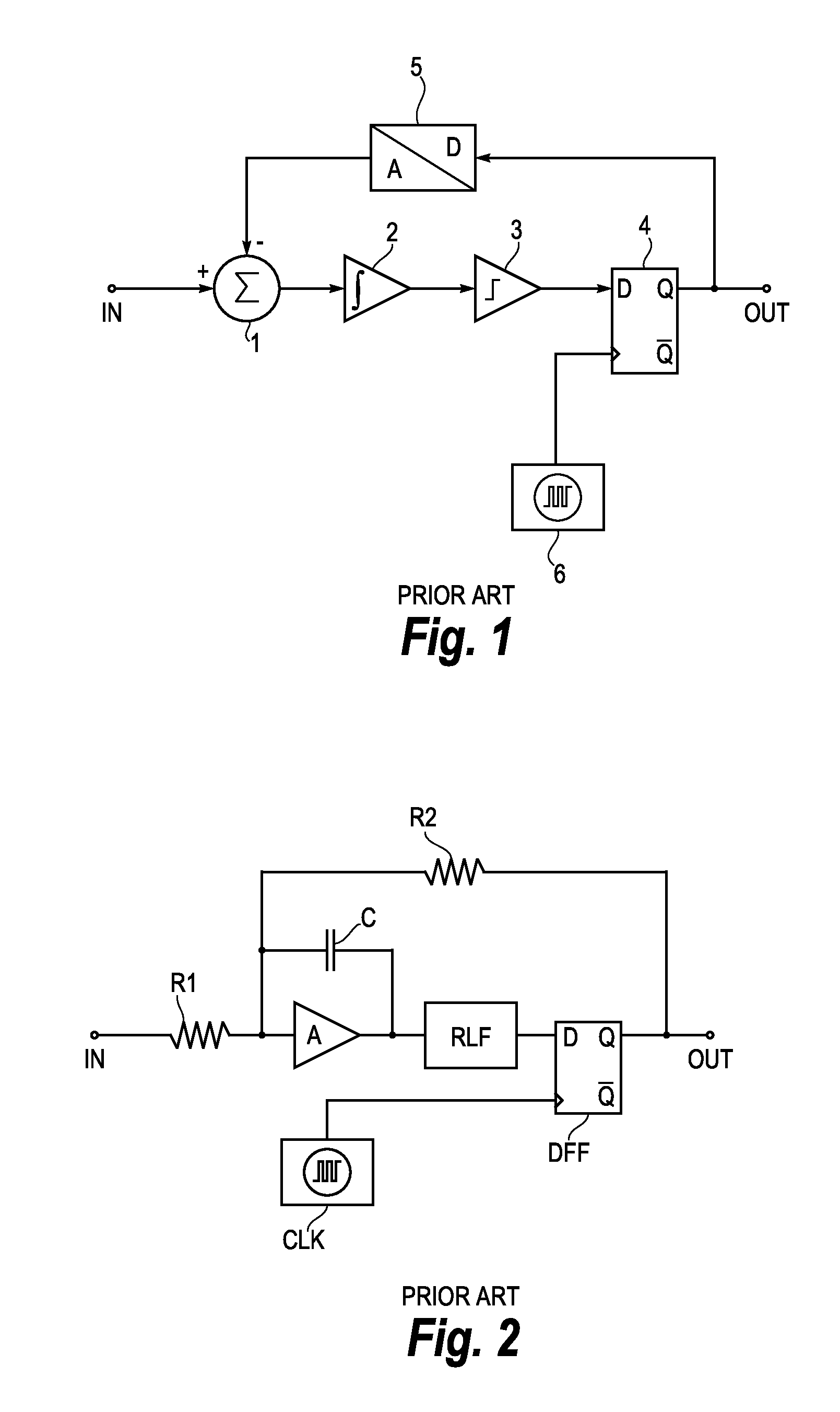
[0034]FIG. 1 shows a block schematic of a prior art delta-sigma A / D converter comprising an input terminal IN, a subtraction point 1, an integrator 2, a comparator 3, a D-flip-flop 4, a 1-bit digital-analog converter 5, a clock generator 6, and an output terminal OUT. An analog signal presented to the input terminal IN is fed to the subtraction point 1 where the output signal from the 1-bit D / A converter 5 is subtracted from the input signal, generating an error signal. The difference signal from the subtraction point 1 is fed to the input of the integrator 2 for generating an integral of the difference signal from the subtraction point 1. The output signal from the integrator 2 is presented to the input of the comparator 3 for generating a logical “one”-level whenever the integral signal exceeds a predetermined threshold limit set by the comparator 3, and a logical “zero”-level whenever the output signal from the integrator 2 falls below the predetermined threshold. This logical si...


PUM


Abstract

In order to minimize noise and current consumption in a hearing aid, an input converter comprising a first voltage transformer and an analog-to-digital converter of the delta-sigma type for a hearing aid is devised. The analog-to-digital converter of the input converter has an input stage, an output stage, and a feedback loop, and the input stage comprises an amplifier (QA) and an integrator (RLF). The first voltage transformer (IT) has a transformation ratio such that it provides an output voltage larger than the input voltage and is placed in the input converter upstream of the input stage. A second voltage transformer (OT) having a transformation ratio such that it provides an output voltage larger than the input voltage, is optionally placed in the feedback loop of the converter. The voltage transformers (IT, OT) are switched-capacitor voltage transformers, each transformer (IT, OT) having at least two capacitors (Ca, Cb, Cc, Cd). The invention further provides a method of converting an analog signal.

Description

RELATED APPLICATIONS[0001]The present application is a continuation-in-part of application No. PCT / EP2009055279, filed on Apr. 30, 2009, in Europe and published as WO2010 / 124737 A1.BACKGROUND OF THE INVENTION[0002]1. Field of the Invention[0003]The present invention relates to hearing aids. The invention, more specifically, relates to analog-to-digital input signal converters in digital hearing aids. The invention further relates to a method of converting an analog signal to a digital signal in a hearing aid.[0004]An analog-to-digital converter, denoted an A / D converter in the following, converts a varying current or voltage into a digital data format. Several different A / D converter topologies exist, each having benefits and tradeoffs in terms of conversion speed, accuracy, quantization noise, current consumption, word length, linearity and circuit complexity. In contemporary, digital hearing aid designs, the delta-sigma A / D converter type is the preferred converter type due to a n...

Claims


Application Information

Patent Timeline
Patent Type & Authority Applications(United States)
IPC IPC(8): H03M3/02H03M1/12
CPCH03M3/43H03M3/484H03M3/486H03M3/458H03M1/002H03M1/12H04R25/505H03M3/02H04R25/00
Inventor KNUDSEN, NIELS OLE
Owner WIDEX AS
Why Eureka
Try Eureka