
Nonaqueous electrolyte secondary battery

Inactive Publication Date: 2012-01-12
HITACHI AUTOMOTIVE SYST LTD
View PDF6 Cites 33 Cited by
  • Summary
  • Abstract
  • Description
  • Claims
  • Application Information

AI Technical Summary

Benefits of technology

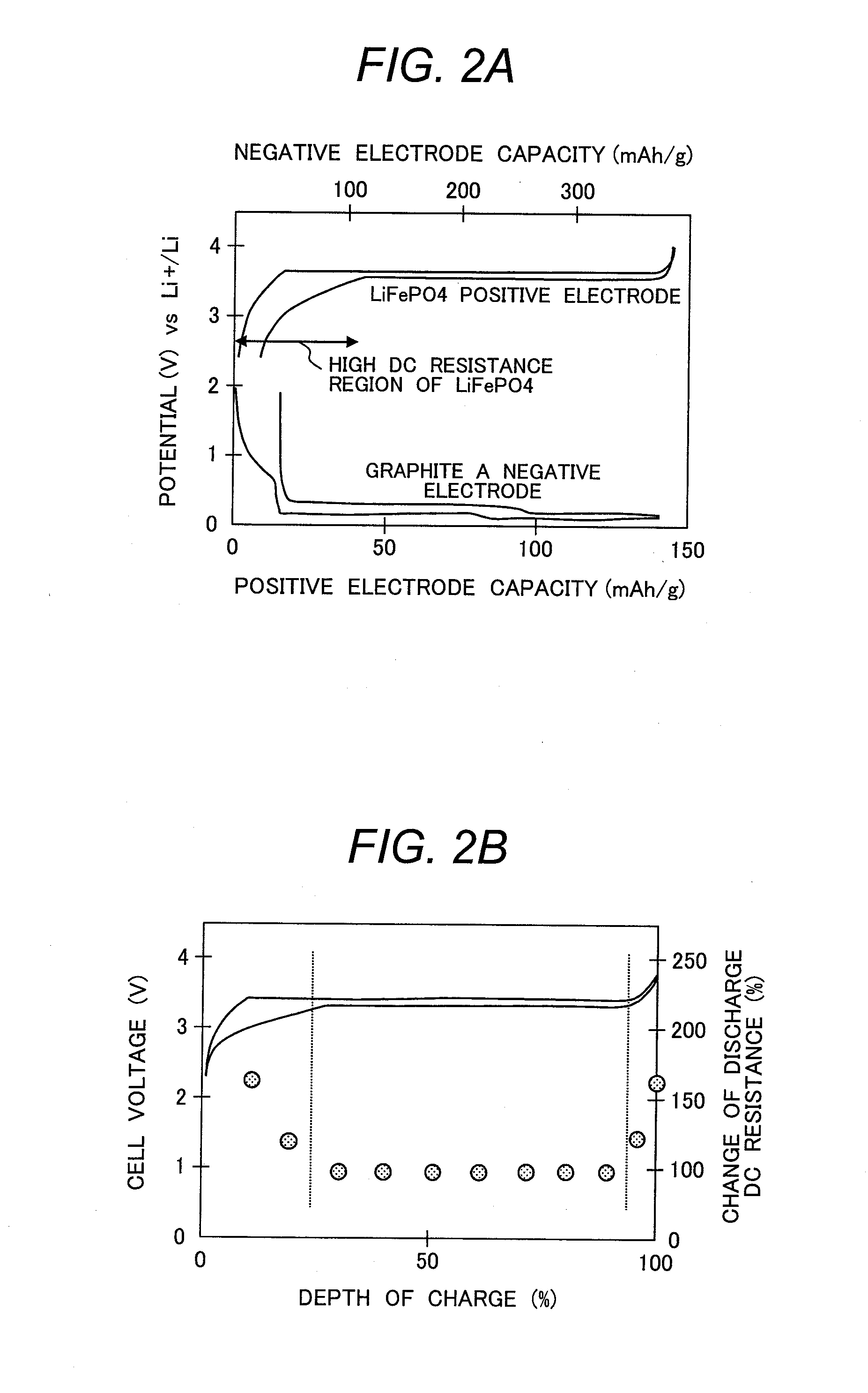
[0016]According to the present invention, the secondary battery has a wider available range of depth of discharge and thereby has a higher energy density, because use of the high resistance region of the lithium metal phosphate is avoided to suppress the secondary battery from having an increased resistance.

Problems solved by technology

However, lithium cobaltate increases the production cost of batteries when it is used, because material cobalt is produced in a small quantity and is expensive.
In addition, such batteries using lithium cobaltate are insufficient in safety upon temperature rise of the batteries during a terminal stage of charging.
However, lithium manganate hardly helps the battery to have a sufficient discharge capacity and often suffers from dissolution out of manganese at elevated battery temperatures, thus being problematic.
Lithium nickelate causes the battery to have a low discharge voltage and to show a poor thermal stability during the terminal stage of charging, thus also being problematic.
However, the lithium iron phosphate has a NASICON structure which is inherently an ion conductor, thereby shows poor electron conductivity and has a rigid crystal structure.
For these reasons, the lithium iron phosphate is known to have poor diffusibility of lithium ions, because the diffusion of lithium ions therein is limited and occurs only in a one-dimensional diffusion path.
The lithium iron phosphate therefore has a high resistance and is not suitable as a battery material.

Method used


Image

  • Nonaqueous electrolyte secondary battery
  • Nonaqueous electrolyte secondary battery
  • Nonaqueous electrolyte secondary battery

Examples


example 1

Mixture of Graphite A and Amorphous Carbon A

[0084]In Example 1, a carbon-hybridized lithium iron phosphate

[0085](LiFePO4) as a positive-electrode active material was prepared in the following manner. Specifically, iron oxalate (FeC2O4.2H2O; supplied by Kanto Chemical Co., Inc.), lithium carbonate (Li2CO3; supplied by Kanto Chemical Co., Inc.), ammonium dihydrogen phosphate (NH4H2PO4; supplied by Kanto Chemical Co., Inc.), and dextrin (supplied by Kanto Chemical Co., Inc.) as a carbon source were pulverized and mixed in a satellite ball mill for 2 hours, the mixture was fired in an argon gas atmosphere at 600° C. for 24 hours, and thereby synthetically yielded a lithium iron phosphate containing 5 percent by weight of carbon. The resulting carbon-hybridized lithium iron phosphate was subjected to X-ray powder diffractometry to verify the absence of heterogenous phases.

[0086]The X-ray powder diffractometry was performed with the RINT 2000 supplied by Rigaku Corporation using the Cu Kα...

example 2

Mixture of Graphite A and Amorphous Carbon B

[0090]Example 2 adopted a positive electrode plate W1 prepared by the procedure of Example 1. A negative-electrode active material used herein was a mixture of Graphite A and Amorphous Carbon B. Graphite A was as with one used in Example 1. Amorphous Carbon B showed an intensity ratio I1360 (D) / I1580 (G) of 1.0 as determined through Raman spectrometry and a specific surface area of 3 m2 / g and had an initial charge capacity of 350 mAh / g and a discharge capacity of 280 mAh / g (charge / discharge efficiency of 80%). Graphite A and Amorphous Carbon B was mixed by weight ratio of 60:40. The specifications of the negative electrode had an initial charge capacity of 344 mAh / g, a negative-electrode initial charge / discharge efficiency e2 of 87%, and a difference x of 12%, as shown in Table 2. How the resistance varies depending on the depth of charge was determined to find that this sample had an available range of charge depth with a resistance chang...

example 3

Mixture of Graphite B and Amorphous Carbon B

[0091]Example 3 adopted a positive electrode plate W1 prepared by the procedure of Example 1. A negative-electrode active material used herein was a mixture of Graphite B and Amorphous Carbon B. Graphite B showed an interlayer distance d002 of 3.370 angstroms as determined through X-ray powder diffractometry and a specific surface area of 0.8 m2 / g and had a charge capacity of 340 mAh / g and a discharge capacity of 320 mAh / g (initial charge / discharge efficiency: 94%). Amorphous Carbon B was as with one used in Example 2. Graphite B and Amorphous Carbon B was mixed by weight ratio of 65:35. With reference to Table 2, the specifications of the negative electrode had an initial charge capacity of 344 mAh / g, a negative-electrode initial charge / discharge efficiency e2 of 89%, and a difference x of 10%. How the resistance varies depending on the depth of charge was determined to find that this sample had an available range of charge depth with a r...


PUM


Abstract

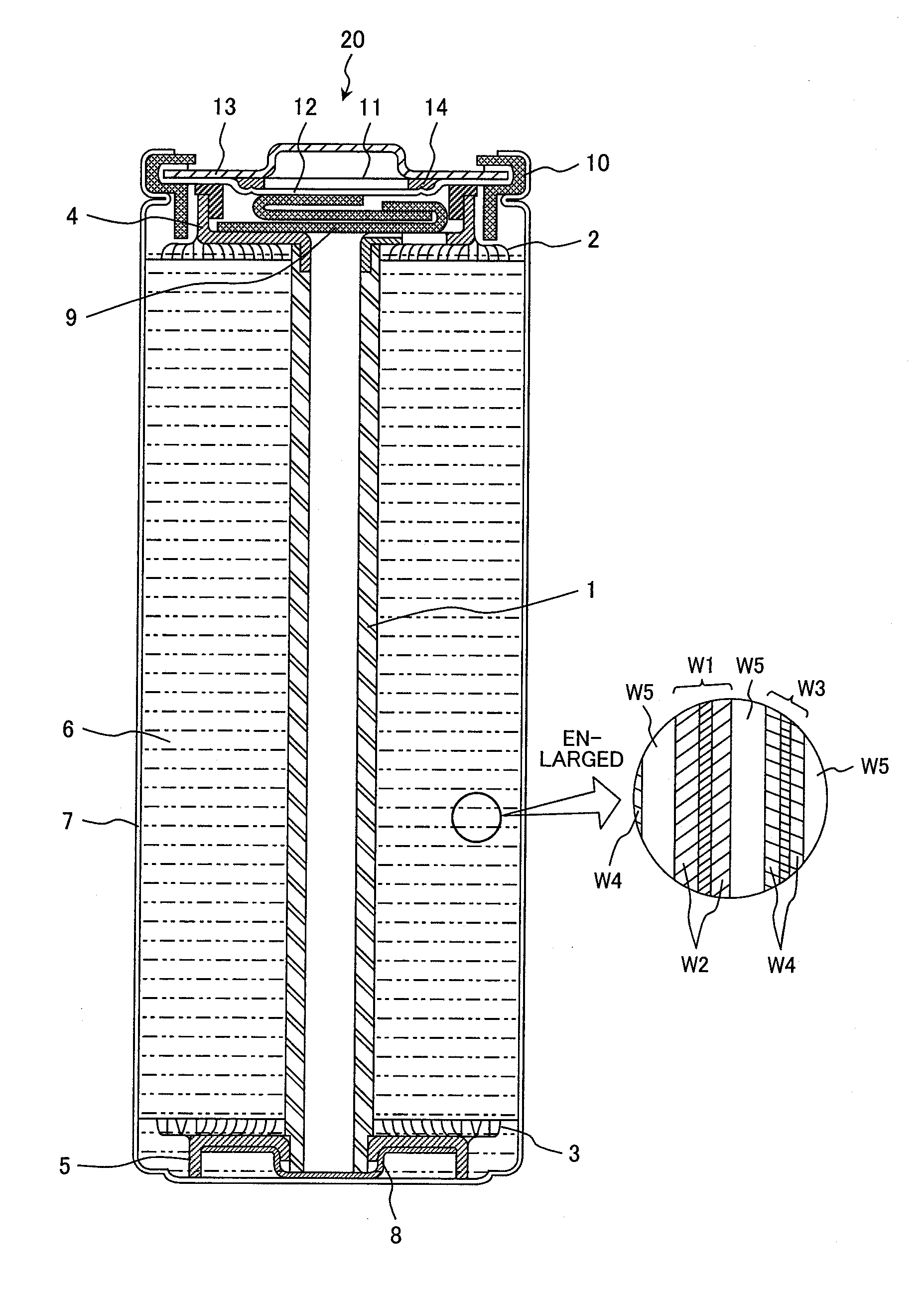
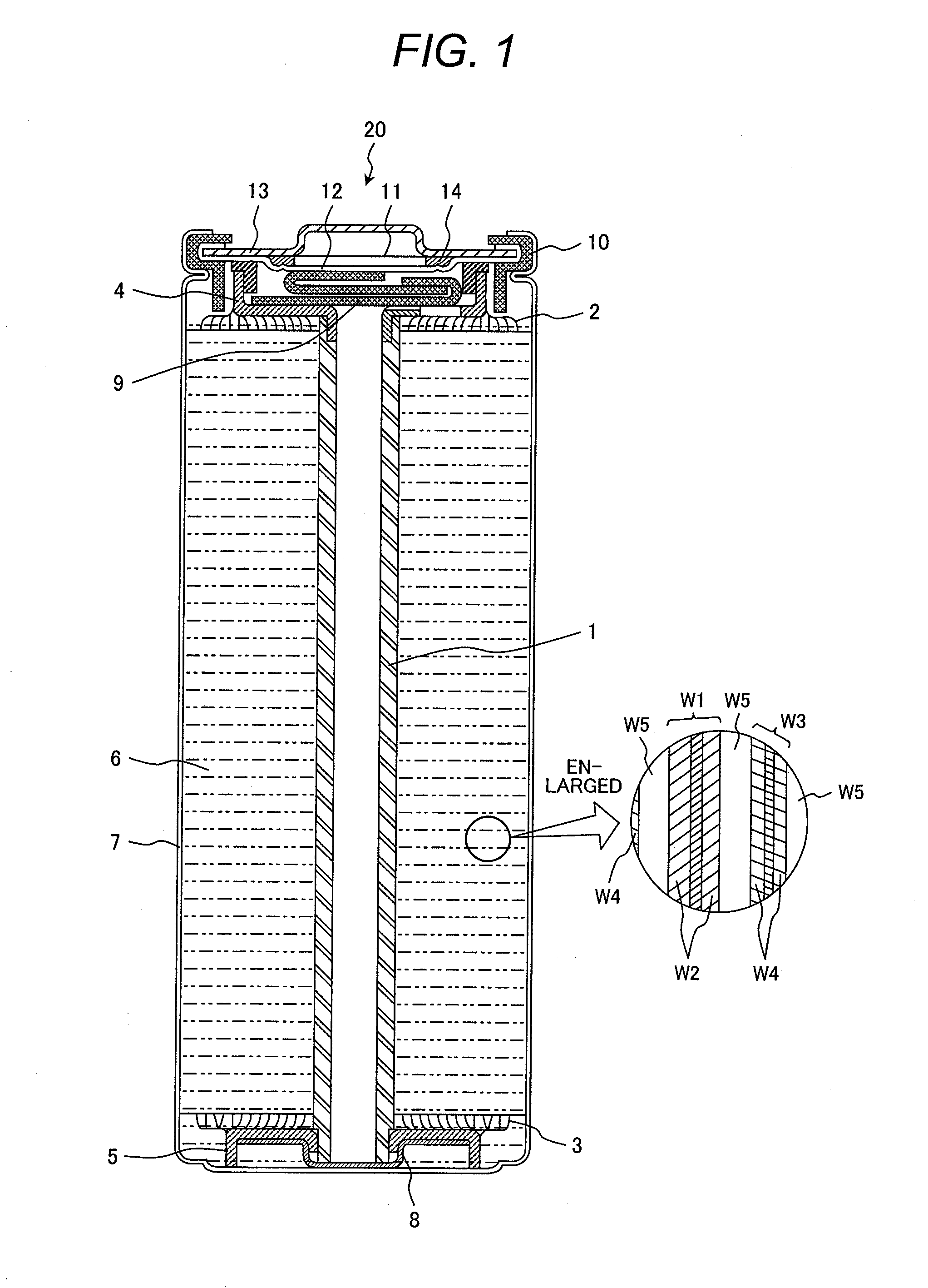
Disclosed is a nonaqueous electrolyte secondary battery wherein the energy density is improved by increasing the range of depth of discharge to be used. Specifically disclosed is a lithium ion secondary battery 20 wherein an electrode group 6 is contained within a battery case 7. The electrode group 6 is formed by winding a positive electrode plate W1 and a negative electrode plate W3 with a separator W5 interposed therebetween. The positive electrode plate W1 has positive-electrode mixture layers W2 which are formed on both surfaces of an aluminum foil and contain a positive-electrode active material. The positive-electrode active material contains lithium iron phosphate as a principal component. The negative electrode plate W3 has negative-electrode mixture layers W4 which are formed on both surfaces of a rolled copper foil and contain a negative-electrode active material. The negative-electrode active material contains a mixture of a graphite material as a principal component and an amorphous carbon material as a secondary component. The positive electrode plate W1 has a positive-electrode initial charge / discharge efficiency of e1, the negative electrode plate W3 has a negative-electrode initial charge / discharge efficiency of e2, and e1 and e2 satisfy the relation of formula e2=e1−x (10≦x≦20). This avoids usage of the high resistance region of the positive electrode plate W1.

Description

TECHNICAL FIELD[0001]The present invention relates to nonaqueous electrolyte secondary batteries. Specifically, the present invention relates to a nonaqueous electrolyte secondary battery including a positive electrode including a positive-electrode active material containing a lithium metal phosphate as a principal component and a negative electrode including a negative-electrode active material containing a graphite material as a principal component.BACKGROUND ART[0002]Customary nonaqueous electrolyte secondary batteries have mostly adopted lithium cobaltate as a positive-electrode active material. However, lithium cobaltate increases the production cost of batteries when it is used, because material cobalt is produced in a small quantity and is expensive. In addition, such batteries using lithium cobaltate are insufficient in safety upon temperature rise of the batteries during a terminal stage of charging.[0003]For these reasons, attempts have been made to use other lithium comp...

Claims


Application Information

Patent Timeline
IPC IPC(8): H01M4/131H01M10/36
CPCH01M4/13H01M4/5825Y02E60/122H01M4/625H01M10/0525H01M4/587Y02E60/10
Inventor UEDA, ATSUSHI
Owner HITACHI AUTOMOTIVE SYST LTD
Learn More