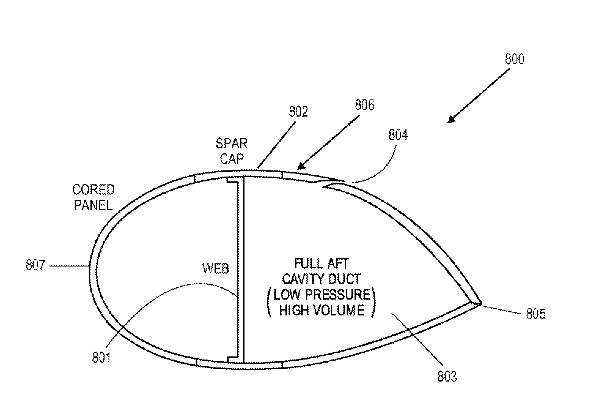
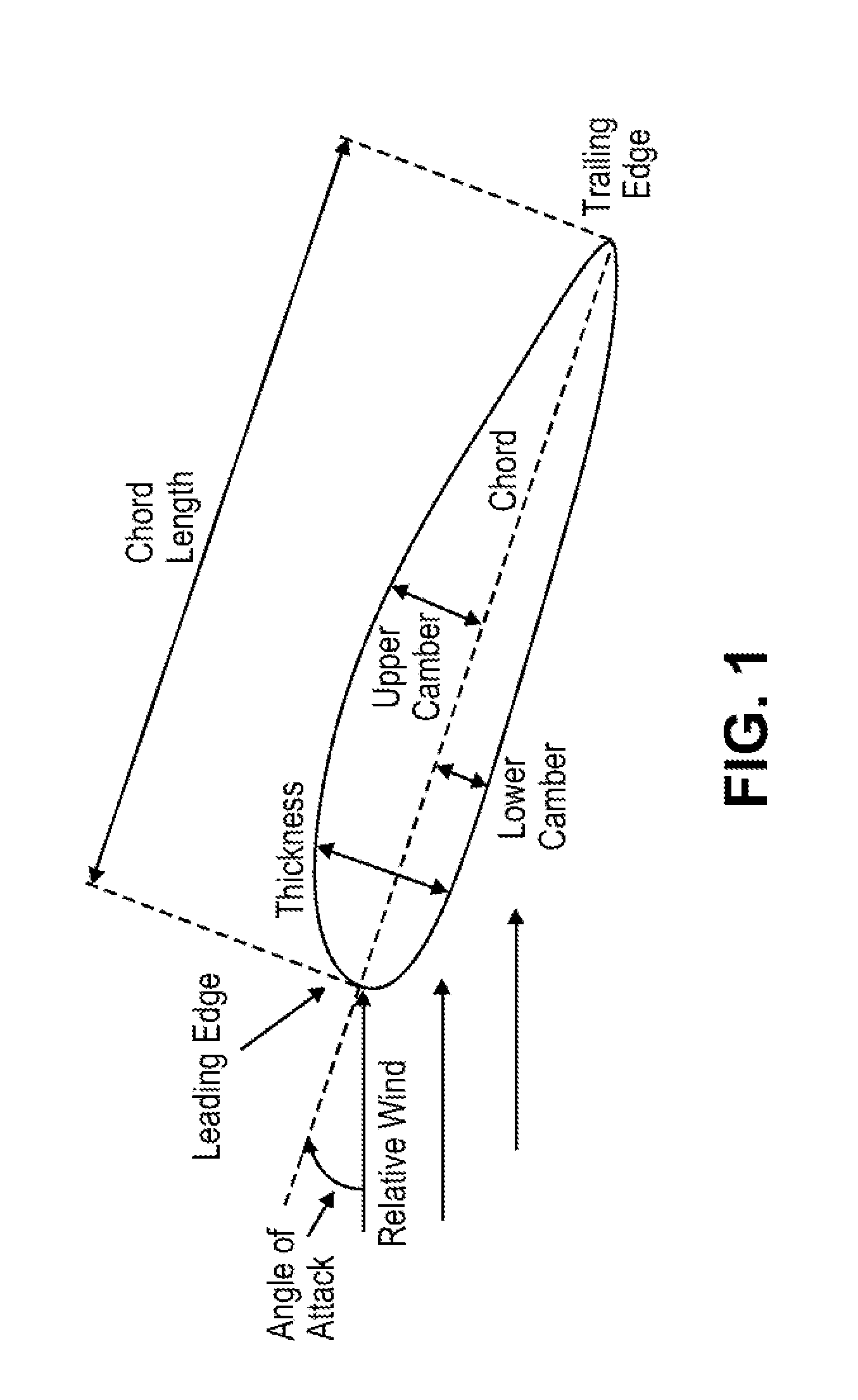
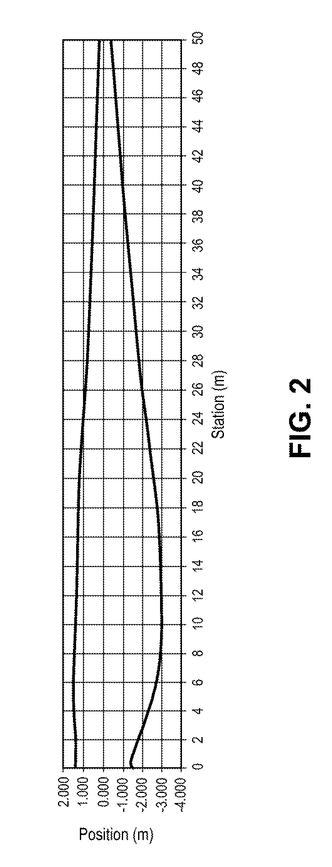
[0006]In embodiments, blades (e.g., turbine blades) are provided that are mechanically simple, highly efficient, structurally strong, cost effective, and controllable for effectively extracting energy from ambient winds. In some cases, this is accomplished by augmenting or controlling the
aerodynamics of turbine blades with the use of pneumatic blowing out of the blades, which may generate forces and extract energy even at substantially low wind velocities. Concurrently, blown blade airfoils are structurally strong and the lift, drag and torque produced by such blades may be made relatively independent of the local
relative wind angle, thus eliminating the
complex problems of
blade pitch and
pitch control mechanisms. Devices provided herein may achieve, among other things, substantially
high lift on specialized blown blades; drag increase (braking) or reduction (efficiency) as required; control of the aerodynamic moments on these blades; prevention of flow separation on these blades (except when flow separation would be desirable, such as for braking); and the ability to perform all of these capabilities without any
physical change in the local blade
angle of attack to the oncoming flow. These capabilities allow energy extraction from the ambient wind over a wider range of wind speeds and local wind
stream angles of
attack on the blades. This will be achieved, for example, with one blowing slot or a plurality of tangential blowing slots located on either end of the individual blade airfoil (
leading edge or training edge), and on either side of the airfoil (pressure or suction side). In addition to very
high lift and reduced drag, thus high
aerodynamic lift / drag ratios and efficiency, these characteristics may be varied by the adjustment of only the blade blowing rates or blowing pressures at these slots.
[0007]Blades, systems and methods provided herein reduce, if not eliminate, the need for blade twist; blade chord change or local
planform area variation (taper); blade camber; and blade variable airfoil geometry, all of which would typically change along the blade span to account for different local wind speeds and wind angles at the various blade radial locations. In some situations, variations in the types of blown airfoils are provided to account for various local conditions.
[0009]In an embodiment, a
turbine blade for use in a wind turbine comprises a pressure side and suction side meeting at a
trailing edge and leading edge, the pressure side having a pressure side surface and the suction side having a suction side surface, the pressure side surface and suction side surface for providing lift to the
turbine blade upon the flow of air from the leading edge to the trailing edge and over the pressure side and suction side surfaces, the pressure side and suction side extending from a root portion to a tip portion of the
turbine blade. The root portion may be operating in a region of ineffective aerodynamic flow, such as a region of flow separation. In some situations, the root portion is substantially non-aerodynamic. The
aerodynamics of blades with substantially non-aerodynamic root portions is improved with the aid or blown passages.
[0011]In another embodiment, a blade configured to be used in a wind turbine comprises a pressure side and suction side meeting at a trailing edge and leading edge, the pressure side having a pressure side surface and the suction side having a suction side surface, the pressure side surface and suction side surface for providing lift to the blade upon the flow of air from the leading edge to the trailing edge and over the pressure side and suction side surfaces, the pressure side and suction side at a root portion of the blade being substantially non-aerodynamic or less aerodynamic in relation to current or convention blades. Such non-aerodynamic or less aerodynamic root portion operates in a region of ineffective flow, such as flow separation or stalled flow. The blade further comprises one or more openings at one of the pressure side and the suction side, the one or more openings for providing aerodynamic shaping to the blade of the wind turbine. The one or more openings may improve the aerodynamic shaping of the blade by providing a pressurized fluid to the suction side and / or the pressure side, which reduces or eliminates flow separation over the blade, including the non-aerodynamic or less aerodynamic root portion of the blade.
[0023]In another embodiment, a
system for controlling the
pitch of a blade comprises a first passageway in fluid communication with a first opening in a pressure side or suction side of the blade, the first opening at an outboard portion of the blade, and a second passageway in fluid communication with a second opening in a suction side of the blade, the second opening at an inboard portion of the blade. The
system further comprises an air
control system in fluid communication with the first and second passageways, wherein the air
control system provides pressurized air to the first and second passageways to control an effective aerodynamic shape of the blade. In some cases, the first opening is at a leading edge of the blade and the second opening at a trailing edge of the blade. The
differential pressure or
mass flow between openings provides positive or negative pitching moment without any blade mechanical
pitch change. This effect may be increased if the openings are also on the opposite sides (pressure side or suction side) of the blade. The
system in some cases includes combined leading edge and trailing edge blowing on the same airfoil. Variable leading edge and trailing edge blowing parameters may allow adjustment (increase or decrease, as desired) of aerodynamic pitching moment on the blade.


