
Delivery of particulate material below ground

a technology of particulate material and discharge pipe, which is applied in the direction of fluid removal, borehole/well accessories, chemistry apparatus and processes, etc., can solve the problem that the amount of gas cannot be increased indefinitely, and achieve the effect of enhancing fracture conductivity, reducing permeability, and reducing permeability

Active Publication Date: 2012-03-01
SCHLUMBERGER TECH CORP
View PDF5 Cites 17 Cited by
  • Summary
  • Abstract
  • Description
  • Claims
  • Application Information

AI Technical Summary

Benefits of technology

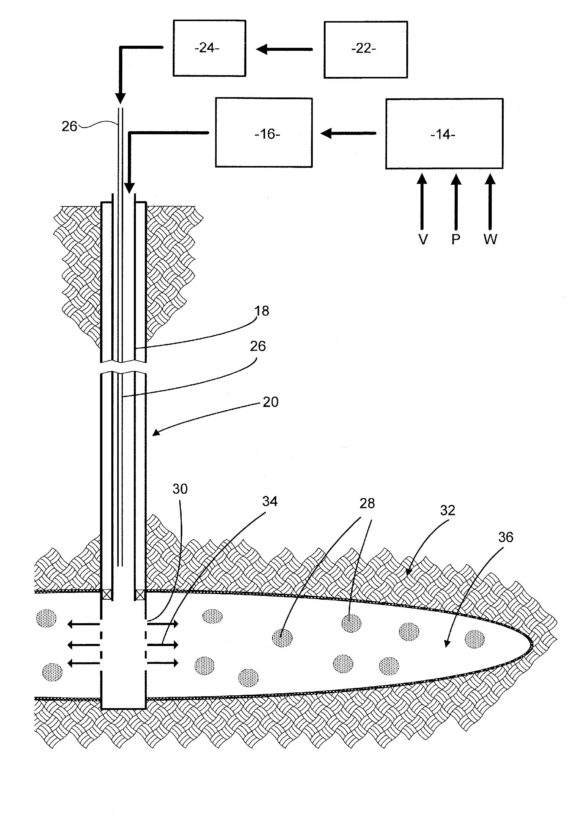
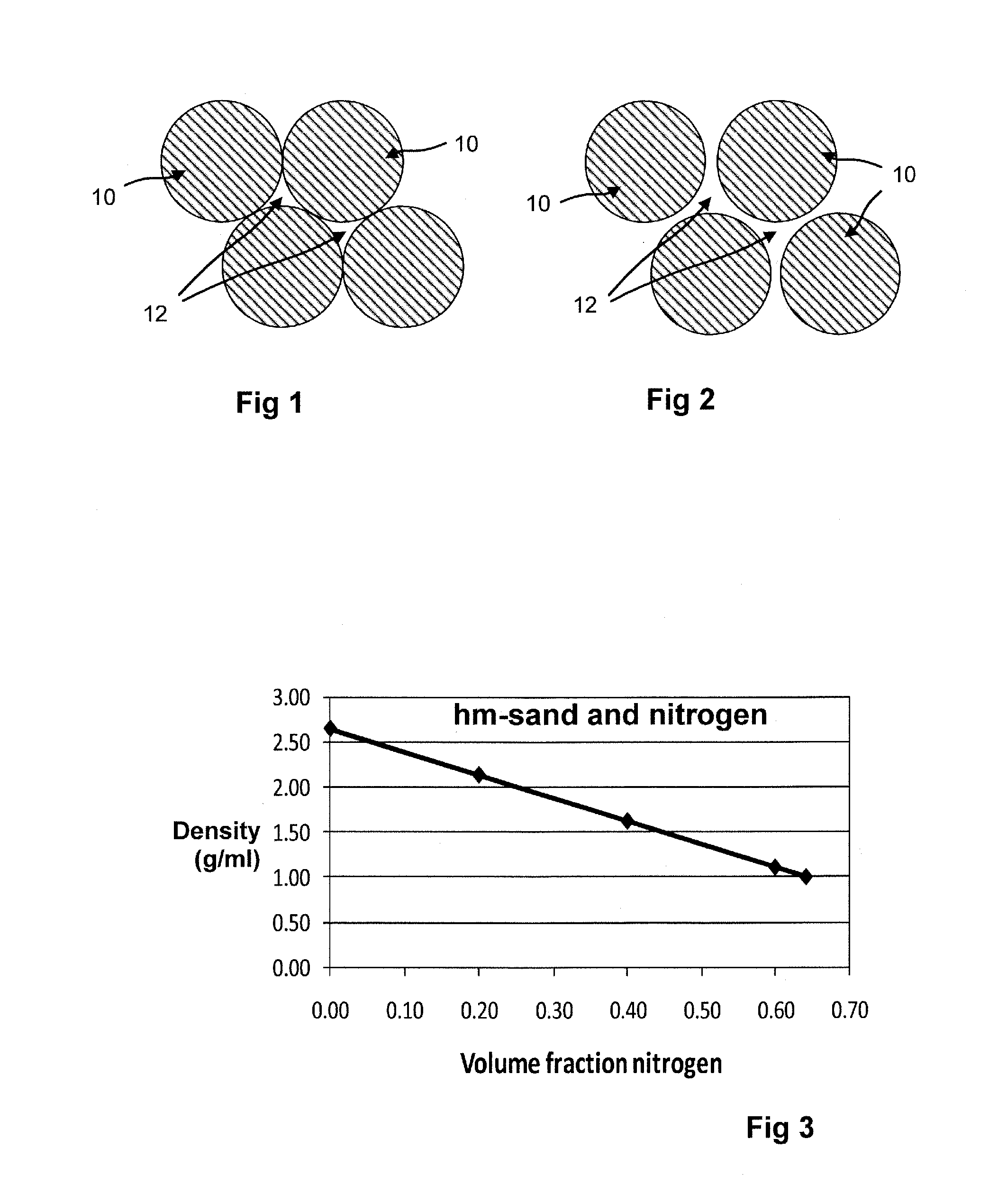
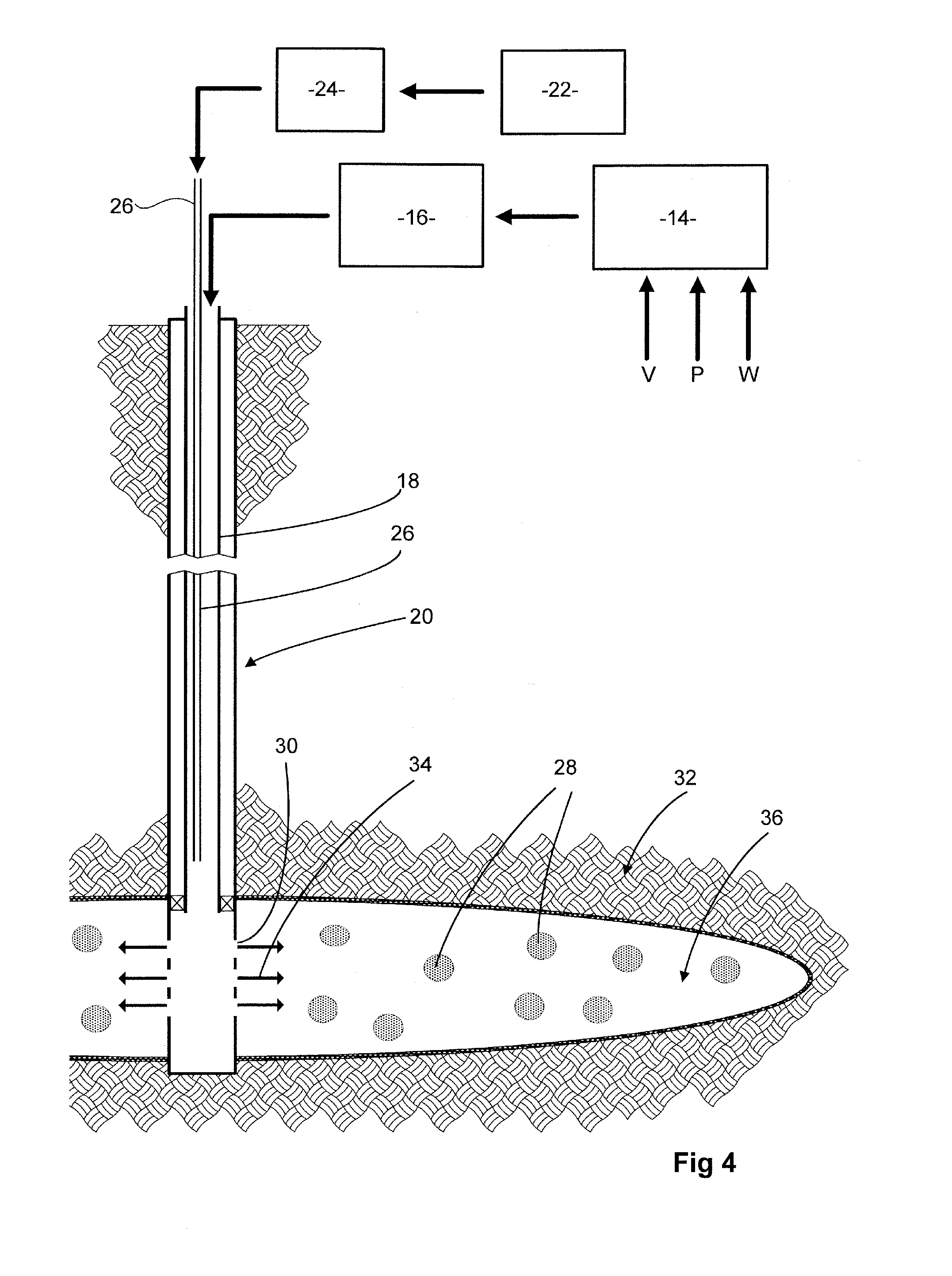
[0011]By agglomerating with gas it is possible to form agglomerates with a bulk density which is lower than the density of the particulate material in them. Because they are of lower density they will settle out of the carrier liquid more slowly. As a result they can be transported more effectively to their intended destination. In the context of hydraulic fracturing the particulate materials can be transported further into the fracture than would be possible if the particulate material was suspended without agglomeration by gas and in consequence a greater length and / or vertical height of fracture (i.e. the fracture area) remains propped open after pumping has ceased. We have found that the amount of gas which can be held in agglomerates has an upper limit. The amount of gas cannot be increased indefinitely. However, we have also found that the amount of gas which can be retained and the concomitant lowering of bulk density are linked to the surface area of the hydrophobic particulate material. The surface area of a particulate material increases as its particle size becomes smaller and in consequence this invention calls for the agglomeration of materials of specified surface area or small particle size.
[0061]Thus, choice of encapsulating polymer in relation to the pH which will be encountered after the particles have been placed at intended subterranean location may provide a control over the delay before the encapsulated material is released. Polymers which are envisaged for use in encapsulation include polymers of hydroxyacids, such as polylactic acid and polyglycolic acid. Hydrolysis liberates carboxylic acid groups, making the composition more acidic. This lowers the pH which in turn accelerates the rate of hydrolysis. Thus the hydrolytic degradation of these polymers begins somewhat slowly but then accelerates towards completion and release of the encapsulated material. Another possibility is that a polymer containing hydrolytically cleavable bonds may be a block copolymer with the blocks joined through ester or amide bonds.

Problems solved by technology

The amount of gas cannot be increased indefinitely.

Method used


Image

  • Delivery of particulate material below ground
  • Delivery of particulate material below ground
  • Delivery of particulate material below ground

Examples


example 1

Toluene Reflux Method

[0071]Sand of the required particle size was washed by mixing with ethanol at ambient temperature, then filtering, washing with deionised water and drying overnight at 80° C.

[0072]Quantities of this pre-washed sand were hydrophobically modified. 75 gm pre-washed sand was added to a mixture of 200 ml toluene, 4 ml organo-silane and 2 ml triethylamine in a 500 ml round bottomed flask. The mixture was refluxed under a nitrogen atmosphere for 4 to 6 hours. After cooling, the hydrophobically modified sand (hm-sand) was filtered off (on a Whatman glass microfiber GF-A filter) and then washed, first with 200 ml toluene, then 200 ml ethanol and then 800 ml deionised water. The hm-sand was then dried overnight at 80° C.

[0073]The above procedure was carried out using both 20 / 40 and 70 / 140 sand and using each of the following four reactive organo-silanes:

[0074]5.64 gm Heptadecafluoro-1,1,2,2-tetrahydro-decyl-triethoxysilane (>95% purity, specific gravity=1.41 gm / ml).

[0075]...

example 2

[0079]The procedure of Example 1 above was also used to bring about hydrophobic modification of two further materials having particle size as given in the following table which also includes size data for the 70 / 140 sand of the previous example.

70 / 140 sandMuscovite micaFine silicad10121 micron 50 micron 6 micrond50169 micron111 micron34 micrond90235 micron200 micron84 micron

[0080]The reactive organosilane used with both of these particulate materials was heptadecafluoro-1,1,2,2-tetrahydro-decyl-triethoxysilane. 75 gm of the particulate solid was treated with 5.89 gm of the reactive silane.

example 3

Condensation Coating

[0081]70 / 140 sand, prewashed as in Example 1 above, was given a hydrophobic surface coating by the simultaneous condensation polymerization of tetraethylorthosilicate (TEOS) and heptadecafluoro-1,1,2,2-tetrahydro-decyl-triethoxysilane in 3:1 molar ratio under basic conditions.

[0082]200 gm pre-washed sand, 12 ml of aqueous ammonia (NH4OH, 28%), 57 ml of absolute ethanol and 3 ml deionized water were mixed and stirred vigorously (Heidolph mechanical stirrer at 300-400 RPM) for 30 min. Then 0.73 gm (3.53 mmol) of TEOS and 0.63 gm (1.17 mmol) heptadecafluoro fluoro-1,1,2,2-tetrahydro-decyl-triethoxysilane were added and stirred for 3.5 hrs at room temperature. The resulting hm-sand was then filtered off, washed with ethanol and then with deionized water and dried at 120° C. overnight.

[0083]This procedure was also carried out using pre-washed 70 / 140 sand with a mixture of tetraethylorthosilicate (TEOS) and octadecyl-trimethoxysilane.

Agglomeration with Gas

[0084]FIG. 1 ...


PUM

PropertyMeasurementUnit
particle size d50aaaaaaaaaa
specific gravityaaaaaaaaaa
viscositiesaaaaaaaaaa

Abstract

A wellbore fluid comprises an aqueous carrier liquid, hydrophobic particulate material suspended therein and a gas to wet the surface of the particles and bind them together as agglomerates. The hydrophobic particulate material has a specified maximum particle size and / or minimum surface area: namely a volume median particle size d50 of not more than 200 micron, determined as median diameter of spheres of equivalent volume and / or a surface area of at least 30 m2 per liter (0.03 m2 per milliliter), determined as surface area of smooth spheres of equivalent volume.The agglomeration of the particles by gas leads to the formation of agglomerates which contain gas and so have a bulk density lower than the density of the particles. This reduces the rate of settling. The fluid is particularly envisaged as a slickwater fracturing fluid in which the suspended particles are proppant. We have found that the small particle size and / or substantial surface area increases the amount of gas which can be retained within agglomerates and so enhances the buoyancy of the agglomerates. The end result is that a greater proportion of a hydraulic fracture is propped open.

Description

FIELD OF THE INVENTION[0001]The invention relates to delivery of particulate material to a location below ground. A significant application is as part of a method of hydraulic fracturing of a subterranean reservoir formation, placing proppant in the fracture so as to keep the fracture open as a flow path. However, the invention also extends to other applications where placing of particulate material underground, notably within subterranean reservoirs, is required. It is envisaged that the invention will be used in connection with exploration for, and production of, oil and gas.BACKGROUND OF THE INVENTION[0002]Placing particulate material at a location below ground is a very significant part of a hydraulic fracturing operation. Hydraulic fracturing is a well established technique for reservoir stimulation. Fluid is pumped under pressure into a subterranean formation, forcing portions of the formation apart and creating a thin cavity between them. When pumping is discontinued the natu...

Claims


Application Information

Patent Timeline
Patent Type & Authority Applications(United States)
IPC IPC(8): E21B43/16C09K8/62
CPCE21B43/267C09K8/70C09K2208/28C09K8/805C09K8/665
Inventor HUGHES, TREVORBARMATOV, EVGENYGEDDES, JILLFULLER, MICHAELDROCHON, BRUNOMAKARYCHEV-MIKHAILOV, SERGEY
Owner SCHLUMBERGER TECH CORP
Learn More