Instream Hydro Power Generator

a technology of hydropower generator and instream hydro power, which is applied in the direction of renewable energy generation, machines/engines, climate sustainability, etc., can solve the problems of increasing the complexity of the apparatus, requiring large rotor dimensions to extract any usable amount of power, and affecting the efficiency of the device, so as to reduce or minimize the effect of reducing or maximizing the transfer of power and smooth acceleration

Active Publication Date: 2012-03-29
MCBRIDE GEORGE F
View PDF3 Cites 19 Cited by
  • Summary
  • Abstract
  • Description
  • Claims
  • Application Information

AI Technical Summary

Benefits of technology

[0010]In view of the above, it is an object of the present invention to provide a turbine apparatus with an intake channel, a rotor, and an exhaust channel designed to smoothly accelerate, redirect and decelerate the fluid flowing through it, while reducing or minimizing (and preferably avoiding) cavitation and turbulence in the flowing fluid, and increasing or maximizing the transfer of power from the flowing fluid to the turbine rotor. Another object of the invention is to provide a configuration of a rotor for such an apparatus, that is designed with rotor channel walls thereof configured along preferably idealized fluid flow streamlines through the rotor channels. It is a further object of the invention to provide a suitable configuration of the intake channel, rotor channels, and exhaust channel of such an instream turbine apparatus deployed in a stream of flowing fluid, so as to increase the kinetic energy of the encaptured fluid, extract power from it, and then regain the static pressure of the fluid that is exhausted or discharged back into the flowing stream at the ambient pressure of the freely flowing stream. Another object of the invention is to provide a relatively small-diameter rotor that rotates at a relatively high rotational speed, to maximize the

Problems solved by technology

The simpler devices like old-fashioned windmills and waterwheels have a very low efficiency and require large rotor dimensions to extract any usable amount of power from the flowing wind or water.
The more advanced turbine designs with a rotor housing and ducts typically need to use movable flow control members that are actively controlled and thereby increase the complexity of the apparatus and are subject to malfunction and breakdown.
Furthermore, the more advanced turbine rotor designs typically require a relatively high pressure head of the flowing fluid.
Because they rely on the static pressure drop across the turbine system, such turbine and rotor designs, however, are not suitable for very low head applications, especially instream deployment of a turbine for extracting power from a fluid flow without barrage or impoundment of the fluid.
The damming of a stream or river destroys the river ecosystem upstream of the dam while potentially flooding large areas of previously existing upland, and can disrupt the natural habitat and spawning of fish and other wildlife in the river.
Similarly, tidal barrage of the natural ebb and flow of the changing tides behind a dam in an estuary or sound, disrupts the natural marine ecosystem.
The side effects of such a tidal barrage have been environmentally undesirable or unacceptable, however.
For example, such instream turbines typically cannot extract power from all of the water that flows through them, because some of the water slips through the spaces between the turbine blades without doing any useful work.
Furthermore, the most common instream turbines typically spin at a low rotational speed and therefore require expensive and complicated gearing arrangements to generate electrical power.
The larger the turbine, the more difficult it i

Method used


Image

  • Instream Hydro Power Generator
  • Instream Hydro Power Generator
  • Instream Hydro Power Generator

Examples


Embodiment Construction

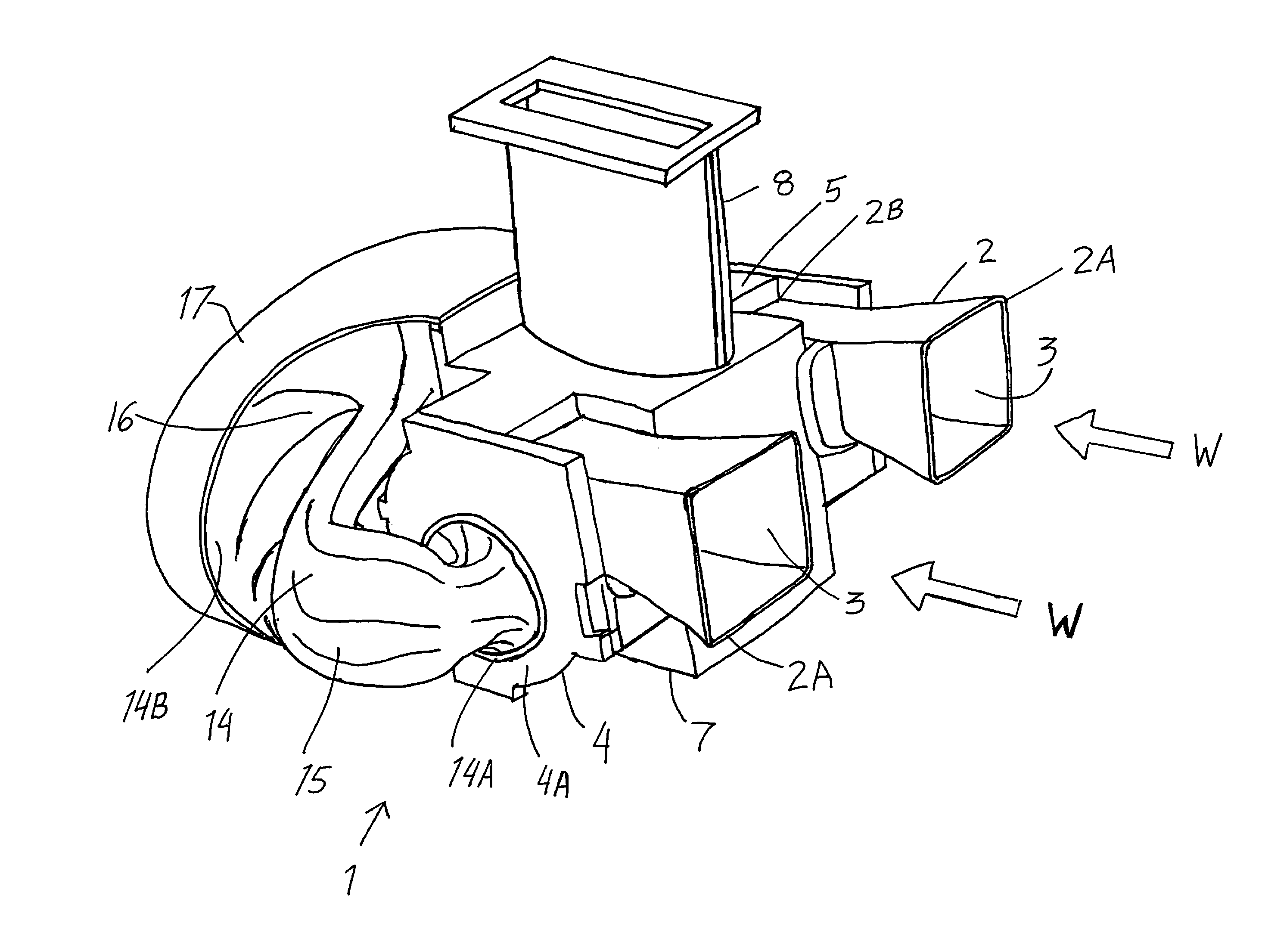
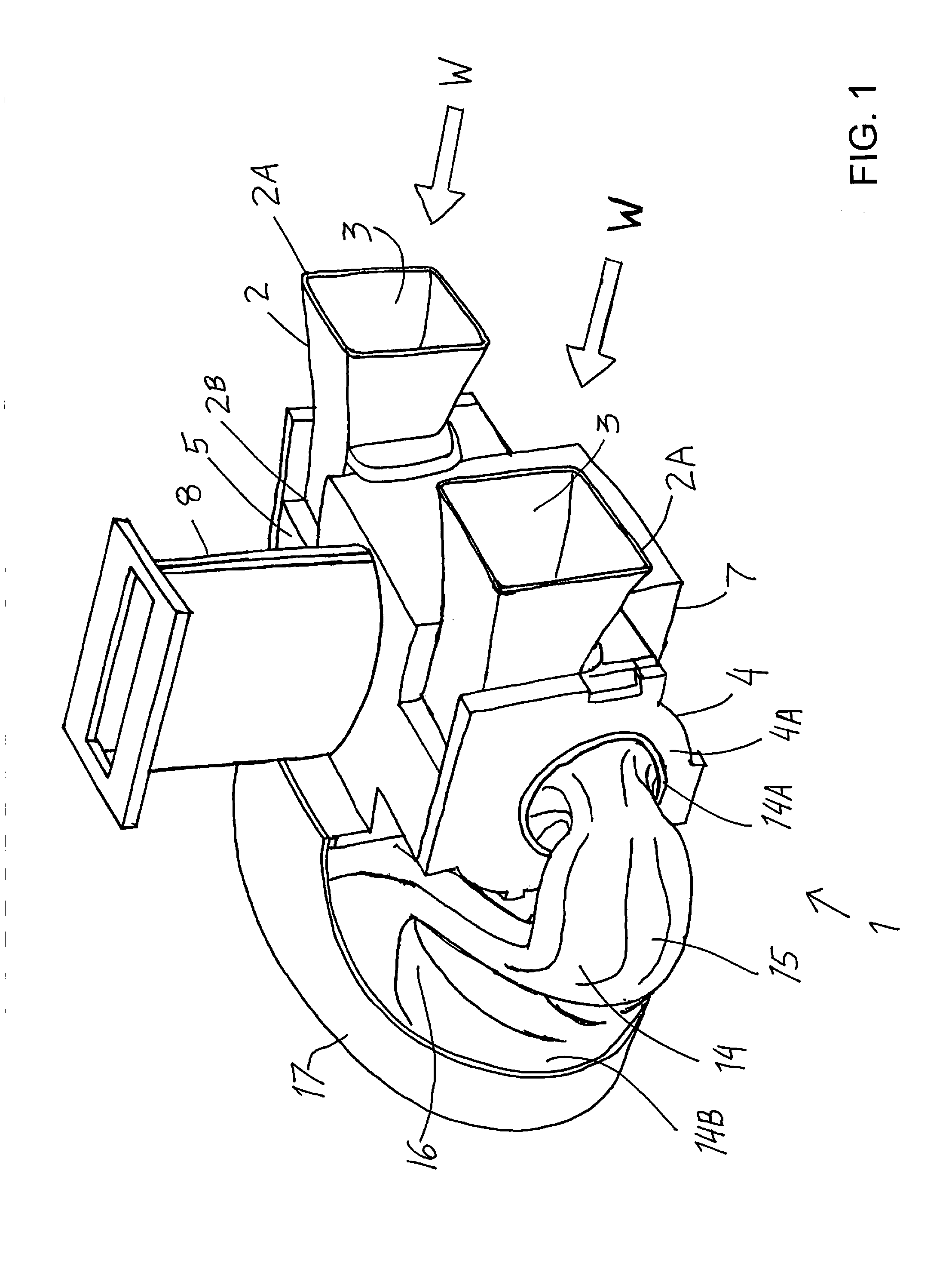
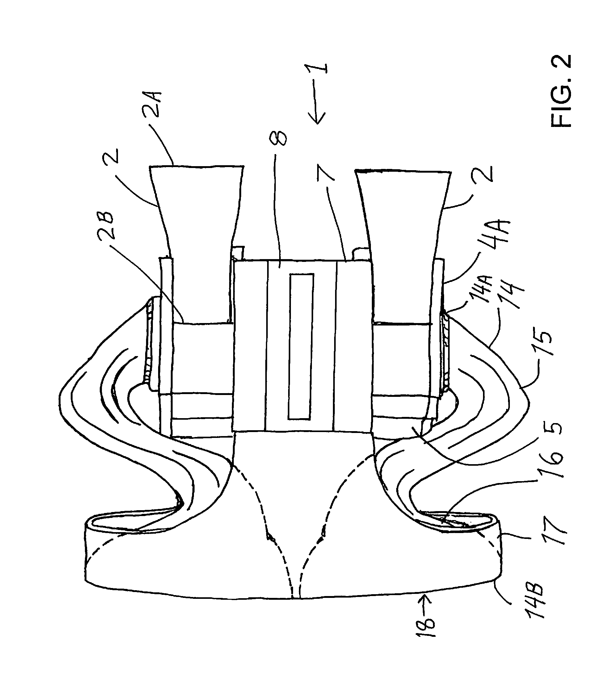
[0046]FIGS. 1 to 5 schematically show the overall construction of an example embodiment of an instream hydro power generator apparatus 1 according to the present invention, which has been built as a prototype. The apparatus 1 is especially adapted and designed to be arranged instream, i.e. immersed in a flowing stream of water W, so as to encapture a portion of the flowing water and extract mechanical power from the encaptured flowing water. However, the invention is not limited to the use of flowing water as the fluid medium from which power is extracted, but rather the inventive teachings can also be applied to a turbine apparatus for extracting power from wind or steam or other flowing fluid media.

[0047]An example of such an instream installation involves the hydro power generator apparatus 1 being secured on a base or pedestal on the seabed in a location where the apparatus will be exposed to tidal flow of ocean water. Alternatively, the instream installation may involve the app...


PUM

PropertyMeasurementUnit
Fractionaaaaaaaaaa
Fractionaaaaaaaaaa
Fractionaaaaaaaaaa

Abstract

A turbine apparatus is immersed in an ambient stream of a flowing fluid, such as water, so as to encapture a portion of the flowing fluid and extract power therefrom, before returning it back into the ambient stream, which may be a tidal flow of ocean water, or a relative flow of water behind a boat. The apparatus includes a converging intake duct with an inlet opening that faces forward into the ambient stream flow, a spiral volute casing that redirects the fluid into a spiral flow, a rotor arranged coaxially on the spiral axis, and an exhaust duct that diverges and curves from an exhaust inlet coaxial with the spiral axis to an exhaust outlet that opens rearwardly into the ambient flow. The rotor has a peripheral rotor inlet around the circumference of a first stage thereof and an axial rotor outlet at one axial end thereof, and is arranged with its rotor axis coinciding with the spiral axis oriented transverse to the ambient stream flow. The rotor redirects the fluid from the spiral tangential and radial direction at the rotor inlet to the axial direction at the rotor outlet, while extracting power therefrom. Fluid flow channels are designed to achieve smooth acceleration, redirection, power transfer, and deceleration of the fluid preferably without turbulence and cavitation, and preferably using streamlines to develop the surface contours of complex channel components.

Description

FIELD OF THE INVENTION[0001]The invention relates to an apparatus deployed in a stream of flowing fluid for extracting power from the fluid into a rotating shaft, a rotor for use in such an apparatus, a method of processing a fluid to extract power therefrom using such an apparatus, and a method of designing such an apparatus.BACKGROUND INFORMATION[0002]For hundreds of years, efforts have been made to harness the power of flowing fluids, and especially the natural flow of streams of wind and water over the surface of the earth. In this regard, various designs of windmills and waterwheels have long been known. In the industrial revolution and thereafter, more sophisticated turbines were developed to improve the efficiency of the extraction of power from the flowing fluid. Turbines were also developed to extract power from steam and hot gases as the flowing fluid. Such turbine apparatuses all include a rotor or runner mounted on a rotatable shaft, and may include a housing around the ...

Claims


Application Information

Patent Timeline
IPC IPC(8): F04D29/44B23P17/00
CPCF03B3/02F03B13/264F03B17/062Y10T29/49229Y02E10/223Y02E10/28F05B2240/97Y02E10/20Y02E10/30
Inventor MCBRIDE, GEORGE F.MCBRIDE, LYLE E.
Owner MCBRIDE GEORGE F
Why Eureka
Try Eureka