Nanocomposites, method for producing same, and use thereof in devices for protecting against electromagnetic waves

a technology of nanocomposites and organic pigments, applied in the field of nanocomposites, can solve the problems of system based on organic pigments, wavelength-selective, and inability to limit in the infrared rang

Inactive Publication Date: 2012-04-19
CENT NAT DE LA RECHERCHE SCI +1
View PDF6 Cites 2 Cited by
  • Summary
  • Abstract
  • Description
  • Claims
  • Application Information

AI Technical Summary

Benefits of technology

[0030]Chloroform will preferably be used as dispersant, due to the stability of the suspension of nanocomposite in this medium. Furthermore, the toxicity of chloroform is much lower than that of carbon disulfide.
[0032]To increase the stability of the suspension of nanocomposite according to the invention in the liquid medium that is transparent to visible and infrared radiation, said medium may comprise one or more surfactants or dispersants, such as polyvinyl acetate (PVA) or sodium dodecyl sulfate.
[0040]d) a step of calcination of said optionally milled gel obtained in step c) at a temperature and for a time of crystallization of the transition metal nanooxide inside the nanomaterials and / or on their walls, while conserving the one-dimensional nature of the nano-materials.
[0048]Placing particles of the nanocomposite according to the invention in suspension in a solvent makes it possible to produce the switching function while limiting the transmission of the incident beam for high fluxes.

Problems solved by technology

Such devices give good results in terms of protection against luminous fluxes with wavelengths ranging from the visible range to the near infrared, but their use poses many problems, and especially that of keeping the carbon particles in suspension.
In addition, such systems are not at all suited to limitation in the infrared range (in particular the medium infrared) since water is a totally absorbent liquid and thus not transparent in the infrared.
Systems formed from filters also exist, which have the drawback of being wavelength-selective.
Systems based on organic pigments also exist, which are expensive materials, synthesized with solvents of substantial toxicity.
The devices described in patent [1] and the scientific publications [2] to [4] have the drawback of lacking stability in suspension, which limits their long-term use under real conditions of protection against an electromagnetic wave, unless they are functionalized by complex and expensive techniques.

Method used


Image

  • Nanocomposites, method for producing same, and use thereof in devices for protecting against electromagnetic waves
  • Nanocomposites, method for producing same, and use thereof in devices for protecting against electromagnetic waves
  • Nanocomposites, method for producing same, and use thereof in devices for protecting against electromagnetic waves

Examples


example 1

on of a Nanocomposite According to the Invention Formed from Carbon Nanotubes Covered and Filled with Niobium Pentoxide

[0082]A nanocomposite according to the invention based on commercial powders of multi-leaflet carbon nanotubes (CNTs) and niobium pentoxide (Nb2O5 / CNT powders) is prepared via the sol-gel route.

[0083]The sol-gel method used in the context of the present invention is based on the hydrolysis and condensation of niobium alkoxides or chlorides in an alcoholic solution in acidic medium. This method, known as “mild chemistry” (on account of the absence of use of pollutant solvents and of harsh experimental conditions), makes it possible to obtain solid particles of nanometric size.

Depilling / Deaggregation of the Bundles of CNT tubes

[0084]20 ml of absolute ethanol are mixed with 20 ml of acetic acid (these products are used without additional purification). The carbon nanotubes are added to the mixture and ultrasonicated for one hour so as to depell the bundles of carbon na...

example 2

ization of the Nanocomposite of Example 1, in Terms of Morphology and Particle Size

Characterization of the Morphology and Structure by TEM

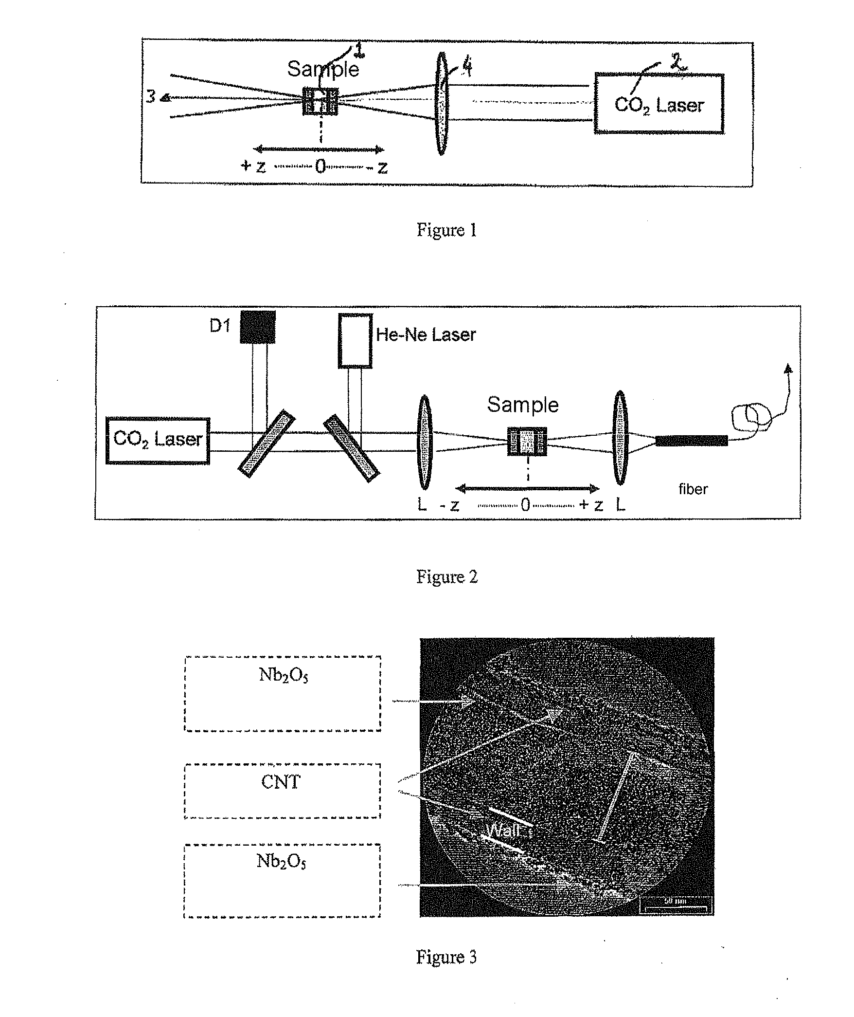
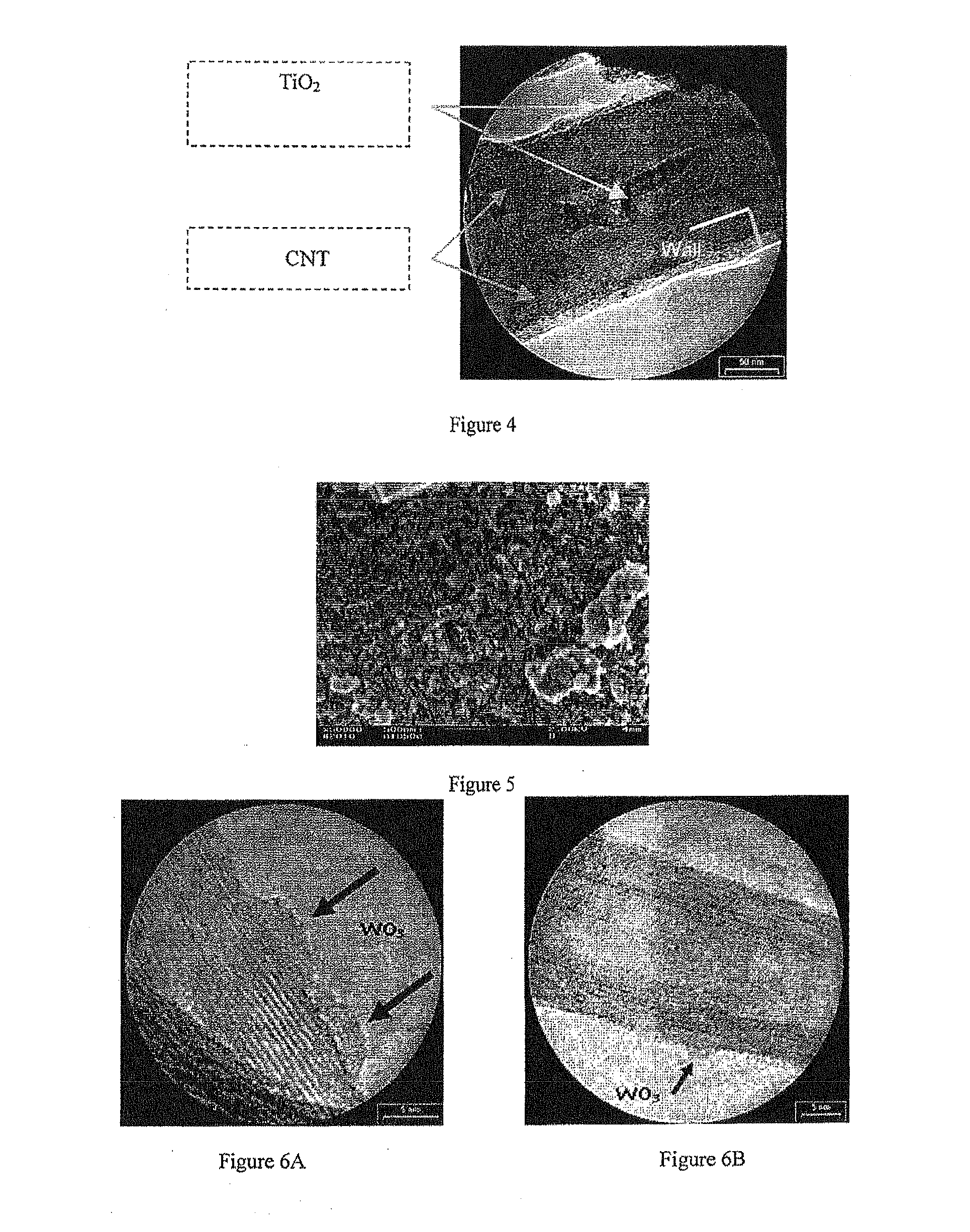
[0092]An image of the structure and morphology of the nanocomposite of Example 1 was obtained by high-resolution transmission electron microscopy (TEM).

[0093]This image presented in FIG. 3 shows that the nanocomposite of Example 1 is formed from carbon nanotubes filled and / or covered with niobium pentoxide.

Characterization of the Size of the Grains by Laser Granulometry

[0094]The nanocomposite of Example 1 is suspended in chloroform at a rate of 2 g / l. The change as a function of time of the mean size of the particles or aggregates of the nanocomposite of Example 1 suspended in chloroform is then recorded by laser granulometry.

[0095]In parallel, the change as a function of time of the mean size of the carbon nanotubes suspended in chloroform (also at a rate of 0.2 g / l) after ultrasonication is also recorded.

[0096]The nanoparticle concentration of e...

example 3

the non-linear behaviour of the nanocomposite of Example 1 (via the Z-SCAN method)

[0099]For this study, the non-linear behaviour of the nanocomposite of Example 1 suspended in chloroform, that of chloroform (solvent) and that of CNTs suspended in chloroform were studied via the Z-scan technique. The concentrations are identical to those used in the particle size measurements.

[0100]The results are presented in FIG. 10, which shows that the energy arriving on the detector (placed just behind the sample) is reduced by more than 60% with the suspension of nanocomposite of Example 1 or of CNTs, when compared with the energy arriving on the detector in the case of a sample containing only chloroform.

[0101]The appearance (FIG. 9) and stability of the suspension of nanocomposite of Example 1 (FIG. 8) are such that they allow it to be used as an optical limiter, in contrast with carbon nanotubes, the latter being of lower stability in suspension.


PUM

PropertyMeasurementUnit
temperatureaaaaaaaaaa

Abstract

A nanocomposite, comprising single-wall and / or multi-wall one-dimensional nanomaterials, and at least one nanooxide of at least one transition metal, said nanooxide filling said nanotubes and covering their walls. A process for preparing such a nanocomposite and an optical limiting device comprising such a nanocomposite in suspension in a medium that is transparent to visible and infrared radiation are disclosed.

Description

TECHNICAL FIELD[0001]The present invention relates in general to a nanocomposite comprising one-dimensional nanomaterials and to applications, especially for protecting against electromagnetic waves.[0002]The present invention relates in particular to a particular nanocomposite, which comprises one-dimensional nanomaterials filled and / or covered with at least one nanooxide of at least one transition metal, to the method for preparing it, and to an optical limiting device comprising such a nanocomposite suspended in a medium which is transparent to visible and infrared radiation. Such an optical limiting device is highly advantageous for applications for protecting against electromagnetic waves ranging from the visible to the medium infrared range.[0003]In the description below, the references in parentheses ([]) refer to the list of references presented after the examples.PRIOR ART[0004]At the present time, the known protection systems based on nanoparticles in suspension cannot be ...

Claims


Application Information

Patent Timeline
Patent Type & Authority Applications(United States)
IPC IPC(8): G02B5/20G02F1/355D01F9/12B82Y20/00B82Y40/00
CPCB82Y20/00Y10T428/2918B82Y40/00C01B31/0273C01B31/0286C01B2202/10C01G23/047C01G23/053C01G33/00C01G41/02C01P2004/04C01P2004/13C01P2004/80Y10T428/2958B82Y30/00C01B32/174C01B32/178
Inventor KELLER-SPITZER, VALERIETEISSIER, ANNELUTZ, YVESMOEGLIN, JEAN-PIERREMULLER, OLIVIERLACROIX, FABRICE
Owner CENT NAT DE LA RECHERCHE SCI
Why Eureka
Try Eureka