External cavity tunable laser module

a laser module and external cavity technology, applied in semiconductor lasers, laser details, electrical equipment, etc., can solve the problems of large economic burden on both users and operators, commercialization of wdm-pon, and the ability to be applied, so as to reduce the cost, increase the production yield, and improve the reproducibility of the wavelength at the time of wavelength tuning

Inactive Publication Date: 2012-04-26
MEL TELECOM
View PDF10 Cites 69 Cited by
  • Summary
  • Abstract
  • Description
  • Claims
  • Application Information

AI Technical Summary

Benefits of technology

[0030]With the wavelength tunable external cavity semiconductor laser module according to the present invention, a semiconductor material based wavelength tunable filter is used and a wavelength-locking function using a temperature sensor and a thermo-electric cooler is provided, thereby making it possible to obtain an oscillating wavelength having stability, reproducibility, and reliability. In addition, the wavelength tunable semiconductor laser module is manufactured by an advanced semiconductor process, thereby making it possible to increase a production yield and reduce a cost. Further, stability and reproducibility of a wavelength at the time of tuning of the wavelength are high due to thermal / mechanical stability of an SOI based silicon optical wavelength, and the wavelength may be reliably tuned even for a long period of time.
[0031]Furthermore, a wavelength reflected by a Bragg grating filter may be precisely and stably controlled and maintained by first and second temperature sensors, a thin film heater, and a thermo-electric cooler, and wavelength-locking characteristics are significantly stable by the precisely controlled and maintained thermal environment and thermal stability of the silicon.
[0032]Moreover, components of an optical module including a light source, an optical waveguide having a Bragg grating formed thereon, a thin film heater, a first temperature sensor, a thermo-electric cooler, and a second temperature sensor are included in a single housing, such that thermal / mechanical stability and durability are high.

Problems solved by technology

The production, installation, and management of the light sources for each wavelength impose a large economic burden on both of users and operators to block commercialization of the WDM-PON.
However, the DFB laser has a wavelength tunable range of 10 nm or less since a relative temperature capable of being applied to an element is significantly restrictive due to gain deterioration.
However, the SG-DBR laser is not appropriate as a low cost light source since an optical amplifier should be additionally integrated in order to compensate for absorption loss by free carriers applied to the Bragg grating region and a manufacturing process is significantly complicated.
In the method of tuning a wavelength as described above, the optical fiber Bragg grating is easily damaged by physical stress and a wavelength tunable range is also not large.
Further, in the case of a technology of utilizing a polymer optical waveguide based wavelength tunable filter using a thermo-optic effect as an output coupler of the external cavity laser, as heat is applied to a polymer material for a long period of time, the polymer material is degraded and local stress is generated due to a temperature gradient, such that a refractive index is changed, thereby deteriorating stability of an oscillating wavelength.
Particularly, it is significantly difficult to secure stability of the level required by a WDM optical communication system having 100 GHz interval.
The change in an effective refractive index of the waveguide due to the above-mentioned cause makes it difficult to a wavelength control of the level required by the WDM optical communication system and limits a wavelength tunable range.
In addition, in the case in which heat is locally applied to the polymer through the metal thin film heating element for a long period of time, the polymer material is degraded and the degraded polymer material again applies stress to the metal thin film heating element, such that the metal thin film heating element is deteriorated and short-circuited.

Method used


Image

  • External cavity tunable laser module
  • External cavity tunable laser module
  • External cavity tunable laser module

Examples


Embodiment Construction

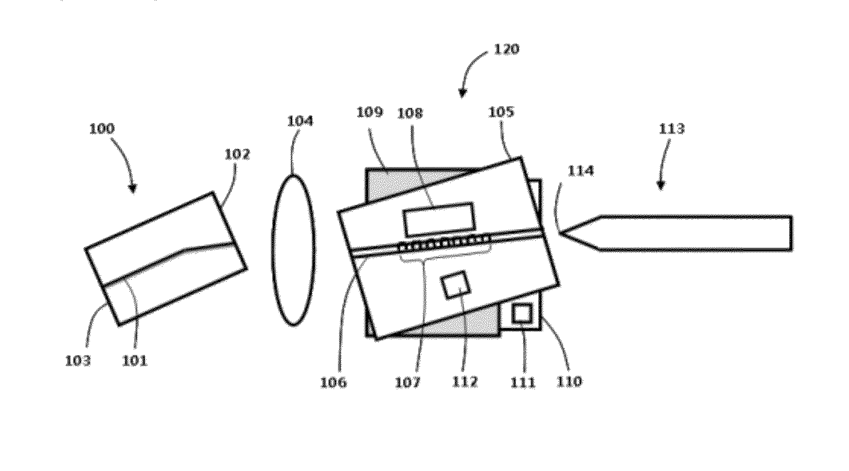
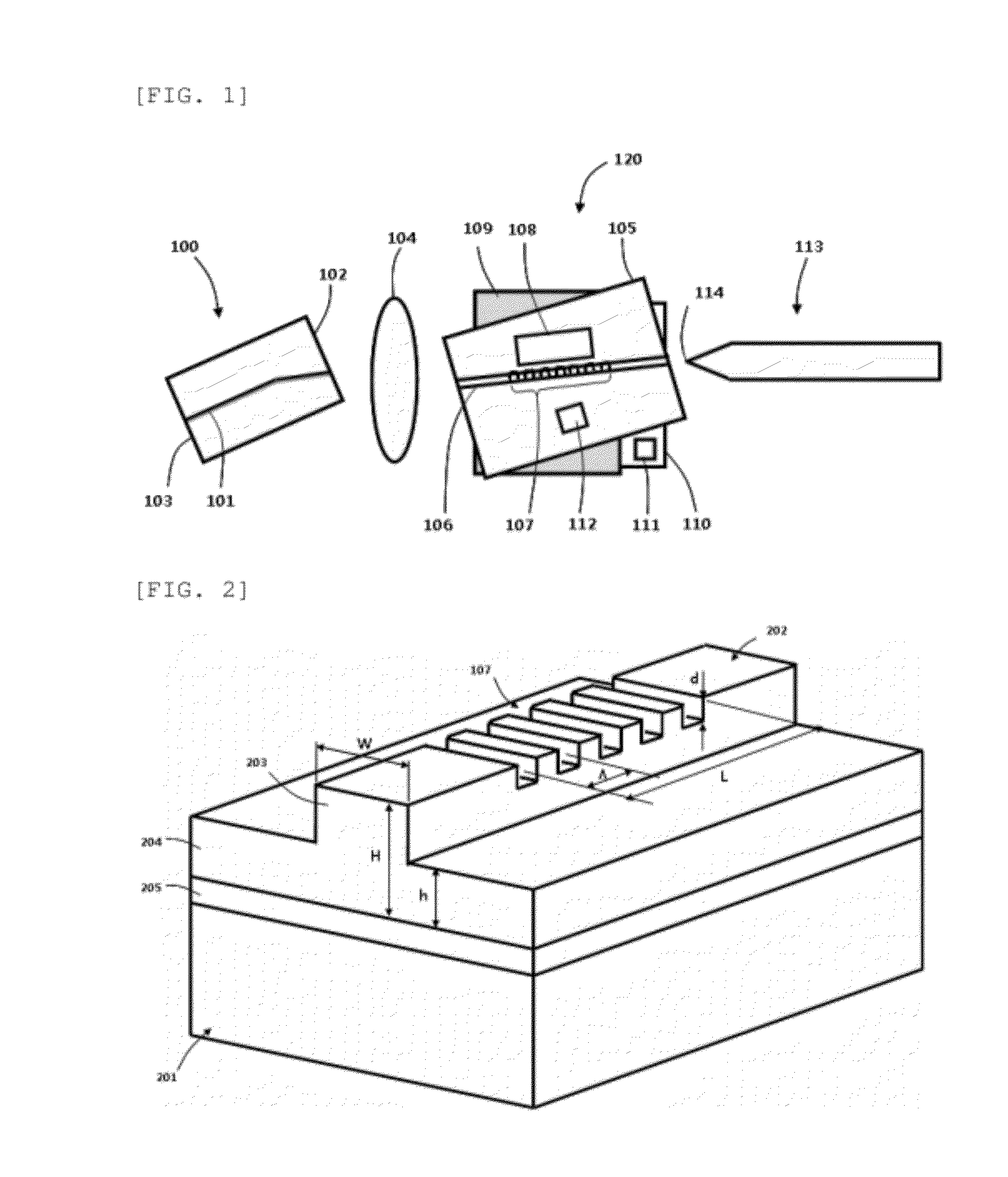
of Main Elements]100: light source120:wavelength tunablefilter105:semiconductor substrate106:semiconductoroptical waveguide107:Bragg grating113:optical fiber110: thermoelectric cooler111:secondtemperature sensor112:first temperature sensor511:housing109:heat insulating layer512: metal layer104, 513:optical coupling lens

BEST MODE

[0044]Hereinafter, a wavelength tunable external cavity semiconductor laser module according to the present invention will be described in detail with reference to the accompanying drawings. The drawings to be provided below are provided by way of example so that the idea of the present invention can be sufficiently transferred to those skilled in the art to which the present invention pertains. Therefore, the present invention is not be limited to the drawings provided below but may be modified in many different forms. In addition, like reference numerals denote like elements throughout the specification.

[0045]Technical terms and scientific terms used in the...


PUM


Abstract

Provided is a wavelength tunable external cavity semiconductor laser module by a thermo-optic effect of a semiconductor optical waveguide. The wavelength tunable external cavity semiconductor laser module includes: a light source generating wideband light; a semiconductor optical waveguide having one end optically coupled to the light source; a Bragg grating formed on the optical waveguide; a thin film heater provided at an upper portion of the Bragg grating and controlling a reflection band of the Bragg grating by a thermo-electric effect; a first temperature sensor provided at an upper portion of the optical waveguide; a thermoelectric cooler (TEC) provided at a lower portion of the optical waveguide; a heat insulating layer provided between the optical waveguide and the TEC; and an optical fiber optically coupled to the other end of the optical waveguide.

Description

TECHNICAL FIELD[0001]The present invention relates to a wavelength tunable external cavity semiconductor laser module capable of being manufactured through an advanced semiconductor process technology, being stably and accurately waveform-tunable, and having excellent long term reliability and reproducibility of an oscillating waveform at the time of tuning of the wavelength.BACKGROUND ART[0002]In accordance with the recent increase in the demand for communication capacity due to the progress of informationization and the diffusion of the Internet, a wavelength division multiplexing (hereinafter, referred to as a WDM) optical system has been developed toward increasing the number of channels according to the densification of an interval between wavelength channels as well as increasing a transmission speed of a light signal in order to increase a bandwidth.[0003]Furthermore, the interest in a WDM based passive optical network (PON) as a method of increasing a communication bandwidth...

Claims


Application Information

Patent Timeline
Patent Type & Authority Applications(United States)
IPC IPC(8): H01S3/10
CPCH01S5/02212H01S5/02284H01S5/02288H01S5/141H01S5/02446H01S5/0287H01S5/1003H01S5/02415H01S5/02253H01S5/02251H01S3/10H01S3/067
Inventor KIM, BYOUNG WHIPARK, MAHN YONGJEONG, GEON
Owner MEL TELECOM
Why Eureka
Try Eureka