
Fomula for Joint Synthetic Jet, Rocket, And Diesel Fuel

a technology of synthetic fuel and fuel injection, which is applied in the direction of fuels, waste based fuels, hydrocarbon oil treatment products, etc., can solve the problems of high freezing point, increase in the price of liquid transportation fuel, and lack of certain properties suitable for jet and diesel fuels. , to achieve the effect of high density and easy ignition

Inactive Publication Date: 2012-04-26
KNIGHT ROY CAMERON +3
View PDF16 Cites 12 Cited by
  • Summary
  • Abstract
  • Description
  • Claims
  • Application Information

AI Technical Summary

Benefits of technology

[0016]Specification for certain jet, rocket and diesel application requires that the fuel utilized have a high density and be easily ignitable and capable of sustaining combustion at temperature of −47 C, and possibly lower. In applications such as jet engines and high altitude rocket engines, specifications also call for fuels having highly reproducible properties. Suitable fuels must also be stable at high temperatures and not deteriorate under a wide variety of shelf-life conditions.

Problems solved by technology

Due to the recent increase in demand for fuel from around the world, and the limited production of crude oil, there has been an increase in the price of liquid transportation fuels.
SPK lack certain properties suitable for jet and diesel fuels, e.g. seal swelling property for o-ring of engines.
More specifically, by way of example, U.S. PreGrant Publication No. 2010 / 0108568 mentioned that straight run FT products have some inherent drawbacks in meeting Jet A-1 and / or Battlefield Use Fuel of the Future (BUFF) specifications, namely a high content of linear alkanes that result in a high freezing point and low temperature viscosity and a low aromatic content.
Although the aforementioned related art provide examples of a fuel or fuel blendstock for jet, rocket, and diesel engines, they involve more complex synthesis or processes in order to produce the desired joint fuels.

Method used


Image

  • Fomula for Joint Synthetic Jet, Rocket, And Diesel Fuel

Examples


Embodiment Construction

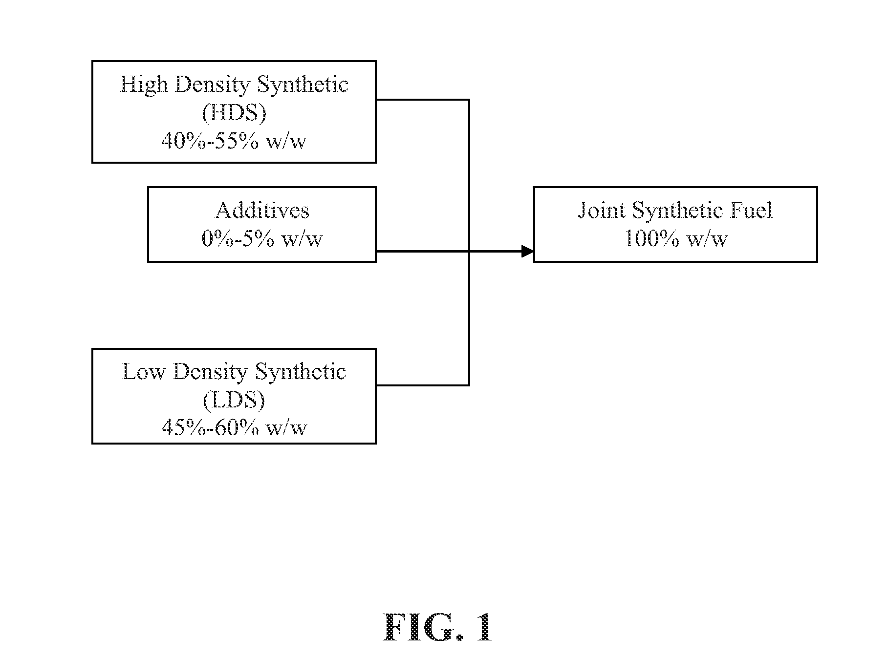
[0024]Referring to FIG. 1, there is disclosed a schematic of the formulation of JSF through blending or co-producing according to one of embodiment of the invention.

[0025]The HDS can be obtained through pyrolysis. The Karrick process is an example of the pyrolysis of coal which leads to retaining of the desired cycloalkane ring and / or hydroaromatic ring structure, which are necessary for certain physical properties, e.g. high density, higher stability in comparison with SPK and good seal swelling property. Particularly, the cycloalkane and hydroaromatic compounds have higher thermal stability relative to the stability of n-alkanes that are major components of the SPK, and thus can attribute to the thermal stability of the jet and diesel fuels. The seal swelling properties is also critical to the gasket o-ring sealing to prevent the jet fuel tank from leaking. The HDS fuel of this invention is essentially Decal in (decahydronapthalene) and Tetral in (tetrahydronapthalene) of which th...


PUM

PropertyMeasurementUnit
coloraaaaaaaaaa
acidityaaaaaaaaaa
flash pointaaaaaaaaaa

Abstract

A synthetic fuel formula using a blend of High Density Synthetic (HDS) (e.g. Decalin and Tetralin), and Low Density Synthetic (LDS) (e.g. Synthetic Paraffinic Kerosene—SPK) is disclosed. This HDS and LDS blend has been shown to be useful as a jet, rocket and diesel fuel of standard density, and under low temperature conditions. The inventions described herein relate to 100% synthetic hydrocarbon fuels derived from various carbonaceous materials such as, but not limited to, biomass, municipal waste, natural gas, and coal. This 100% synthetic fuel can be universally used for both jet and diesel fuels. It meets Joint Battlefield Use Fuel of the Future (J-BUFF), or Single Battlefield Fuel (SBF) strategic requirements. The commercial advantage of the present invention is that it can be prepared from commercial available fuel stocks or co-processed using currently available chemical processes.

Description

BACKGROUND OF THE INVENTION[0001]1. Field of the Invention[0002]The present invention relates to the field of a joint synthetic fuel formula for jet, rocket, or diesel engines, which contains a blend of high density synthetic (HDS) and low density synthetic (LDS) fuels.[0003]2. Description of Related Art[0004]Modern civilization is heavily dependent on crude oil for producing chemical feedstocks and petroleum fuels typically used in combustion engines. Due to the recent increase in demand for fuel from around the world, and the limited production of crude oil, there has been an increase in the price of liquid transportation fuels. In order to increase production of liquid fuel, low cost alternative fuels are needed to meet the ever increasing demand.[0005]There is a vast amount of prior art available regarding non-fossil fuel denoted as carbonaceous feedstocks that can be used for the production of synthetic transportation fuel. Some of the more common carbonaceous feedstocks are co...

Claims


Application Information

Patent Timeline
Patent Type & Authority Applications(United States)
IPC IPC(8): C07C13/48
CPCC10G1/02Y02E50/13C10G2300/1011C10G2300/1022C10G2300/30C10G2300/302C10G2300/307C10G2400/04C10G2400/06C10L1/08Y02E50/32C10G2300/1003C10G2300/1025C10G2400/08Y02T50/678C10G2/30Y02E50/10Y02E50/30Y02P30/20
Inventor KNIGHT, ROY CAMERONONJUKKA, LORI L.ONJUKKA, ROLF L.PARRACK, YVONNE MAE
Owner KNIGHT ROY CAMERON
Learn More