Apparatus and method of fluid aspiration

Active Publication Date: 2012-05-17
BIOMETRIX
View PDF6 Cites 45 Cited by
  • Summary
  • Abstract
  • Description
  • Claims
  • Application Information

AI Technical Summary

Benefits of technology

[0013]The present invention provides an inline blood aspirating system that can operated both manually and automatically; works in a microbial closed manner; enables the return of aspirated fluids to a patient; incorporates an integrated pressure sensor to monitor the patient's blood pressure; results in simplicity of operation and reduction of expenses caused in duality of systems, one for aspiration and one for blood pressure sensing; operates simply and sin

Problems solved by technology

This procedure may be physically strenuous due to the resistance of the gasket inside the syringe which may lead to accidental over aspiration.
This sleeve moves during aspiration, which can lead to ruptures or disengagement of the sleeve resulting in breach of the closed system.
This is cumbersome in a hospital setting, and especially strenuous on a patient's arm.
However this syringe requires two independent squeezing motions instead of one, is not inline, and thus requires an additional valve system.
As a result high torque is exerted on a patient's arm (or stand) and could mask resistance of the fluid line due to occlusions.
In addition this apparatus does not operate in-line and therefore requires an additional valve system, and is cumbersome to clean after aspiration.
The exact amount of fluid aspirated is hard to determine as this apparatus does not incorporate a scale or any other measurement means.
U.S. Pat. No. 6,159,164 discloses a blood sampling system that does not operate in-line and therefore requires an additional valve system, and is cumbersome to flush and clean after aspiration.
The exact amount of fluid aspirated is hard to determine as this apparatus

Method used


Image

  • Apparatus and method of fluid aspiration
  • Apparatus and method of fluid aspiration
  • Apparatus and method of fluid aspiration

Examples


Embodiment Construction

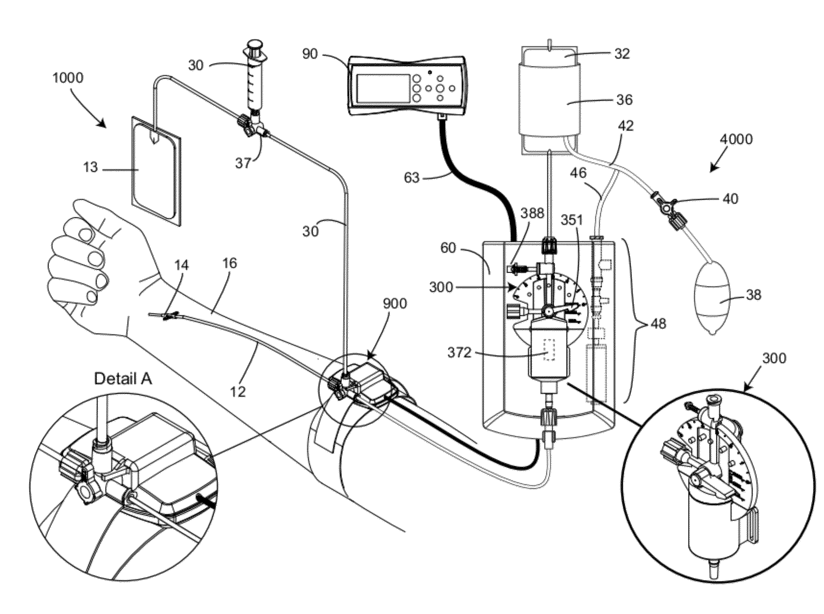
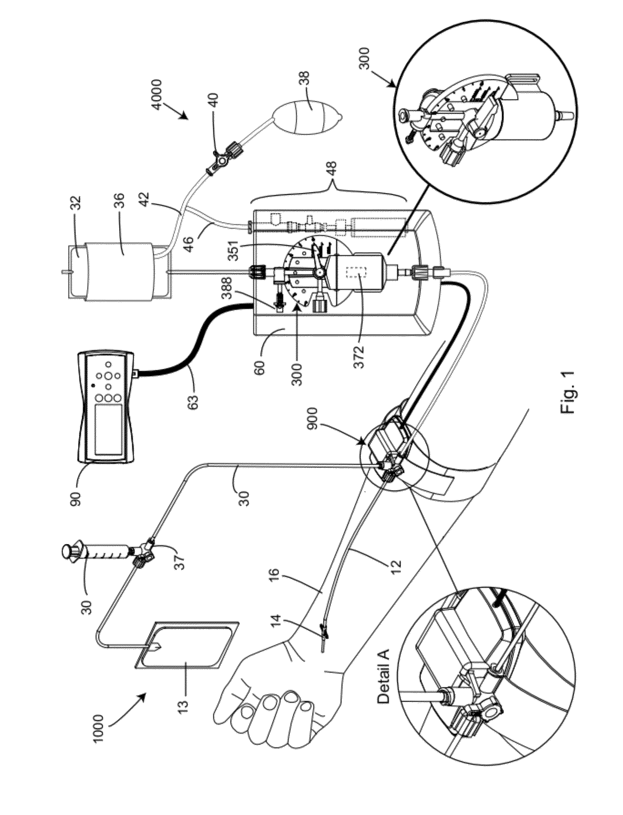
[0048]A preferred embodiment of the blood sampling system of the present invention is shown in FIG. 1, referred generally as 1000, and consists of an automatic blood pressure measuring system with a sampling mechanism. System 1000 consisting of an IV bag (32) connected to a fluid line (12) leading from a catheter (14) embedded in a patient's arm (16). System (1000) comprises a sampling port mechanism (900) shown enlarged in Detail A, which is connected via side tube (35) to a stopcock valve (37) connected to a sampling collecting syringe (30) or any other sample collecting vessel (not shown) and through extension line (33) to a fluid waste collection bag (13) for in line analyzing of blood samples, which will be described in details hereinafter. A syringe (300) is mounted on an electronic apparatus (60). A cable (63) leads from the electronic apparatus (60) to a remote controller and display (90). The remote controller (90) controls the synchronization between sample port (900) and ...


PUM


Abstract

An in-line sampling system that includes a sampling valve and a syringe for selectively introducing a fluid to and aspirating a fluid from a downstream fluid conduit connected to a catheterized patient. The syringe has a fluid chamber into which fluid is aspirated, a volume regulator for adjusting the volume, a fluid line through which fluid flows through the syringe to a downstream fluid conduit. The syringe also has a valve mechanism for selectively controlling fluid flow along the fluid line and selectively shifting the volume regulator to adjust the volume of the fluid chamber. A housing provides for the fluid chamber and mounts the fluid line, valve mechanism and volume regulator.

Description

RELATED APPLICATIONS[0001]This application is a continuation in part of PCT International Patent Application No. PCT / US2010 / 037043 filed Jun. 2, 2010, designating the United States of America and claiming priority from U.S. Provisional Patent Application No. 61 / 183,886 filed Jun. 3, 2009. This application also claims the benefit of U.S. Provisional Patent Application No. 61 / 414,427 filed Nov. 17, 2010, under 35 USC §119(e). The entire contents of each of the aforementioned applications are hereby incorporated by reference herein.BACKGROUND OF THE INVENTION[0002]1. Field of the Invention[0003]The present invention relates to an In-Line sampling device and method for withdrawing (aspirating) blood from a patient fitted with a blood vessel catheter. More particularly, the present invention relates to a syringe enabled for aspirating blood into a sampling site in a closed manner, sealed from ambient air, in order to reduce the risk of human error and cross contaminations during the samp...

Claims


Application Information

Patent Timeline
IPC IPC(8): A61B5/153
CPCA61B5/1427A61M2206/11A61B5/150213A61B5/150221A61B5/150229A61B5/150236A61B5/150862A61B5/150946A61B5/150992A61B5/153A61B5/155G06F19/3468A61M5/1452A61M39/223A61M2005/14533A61M2039/0009A61M2039/0018A61B5/15003G16H20/17
Inventor MENDELS, YAIRUZIEL, ELADMATAN, SHAMIRREVZIN, ILYARUBINSTEIN, ELDAD GABRIELAFRAMIAN, VEREDGERSHUNI, YEHONATANMARCO, ORGA
Owner BIOMETRIX
Why Eureka
Try Eureka