Binder for lithium ion rechargeable battery cells

Active Publication Date: 2012-05-31
SK ON CO LTD
View PDF3 Cites 17 Cited by
  • Summary
  • Abstract
  • Description
  • Claims
  • Application Information

AI Technical Summary

Benefits of technology

[0015]It is an object of the present invention to find a binder that can satisfactorily bind together a range of particulate silicon material, and especially particles made of the relatively cheap “lower grade” silicon, in the electrode of a rechargeable lithium ion cell over a substantial number of discharge / recharge cycle before losing its capacity to hold a charge, despite the large volume changes associated with the insertion and removal of lithium ions into the silicon material during such cycles.
[0016]Surprisingly, it has been found that poly(acrylic acid) (PAA) is a good binder for particulate silicon material in an electrode of a rechargeable lithium ion cell despite the large volume changes associated with the discharging / recharging cycles and that it can be used with both high purity (99.90% pure or above) silicon and lower purity (less than 99.90% pure) silicon.
[0024]In contrast to NaCMC, the acrylic binders of the present invention can be used with all grades of silicon in a Li-ion electrode and enable a stable cycle life performance whilst also overcoming the potential instability of the NaCMC binder to impurity elements that can be present in lower cost grades of silicon.

Problems solved by technology

U.S. Pat. No. 6,399,246 teaches that poly(acrylic acid) does not provide good adhesive properties in graphite anodes of lithium-ion battery cells and claims the use of a polyacrylamide binder.
The volume changes are much larger than in the corresponding graphite anodes and can result in individual silicon particles not always re-establishing electrical contact with each other and with a current collector when the silicon anode shrinks due to the removal of lithium ions during discharging.
However, such silicon is very expensive.
When using relatively cheap, lower-grade silicon, there are minor amounts of impurities present that are not chemically compatible with the binder solution and that cause a decrease in the viscosity of the silicon / binder mixture.
As a consequence, the resulting coating does not retain sufficient contact with the current collector so as to undergo anything more than a limited number of discharge / recharge cycles, before losing its capacity to hold a charge.

Method used


Image

  • Binder for lithium ion rechargeable battery cells
  • Binder for lithium ion rechargeable battery cells
  • Binder for lithium ion rechargeable battery cells

Examples


example 1

Preparation of Electrodes and Testing of Binders

[0039]A series of binders were tested by making up anodes using silicon powder as the active material, the binder set out in Table 2 and a conductive carbon black (Super P® carbon black obtained from TIMCAL, Strada Industriale, CH-6743 Bodio, Switzerland, or Denka Black obtained from Denka (Denki Kagaku Kogyo Kabushiki Kaisha, Tokyo) or a mixture thereof) in a ratio of silicon active material:binder:carbon black of 80:8:12 (wt %) or 76:12:12 (wt %). The polymer solutions are pre-made by dissolving the polymer solid material into the appropriate solvent either water or an organic solvent, as set out in Table 2. Specific composite mixes commence with dispersion of the relevant wt. % of the Si active material into a 10-15 wt % bead-milled solution of the carbon black (Super P carbon or Denka Black) by shear stirring for 12 hours. The relevant wt % of polymer solution is then added to this and the resulting composite is subjected to Dual A...

example 2

Measuring First Cycle Loss

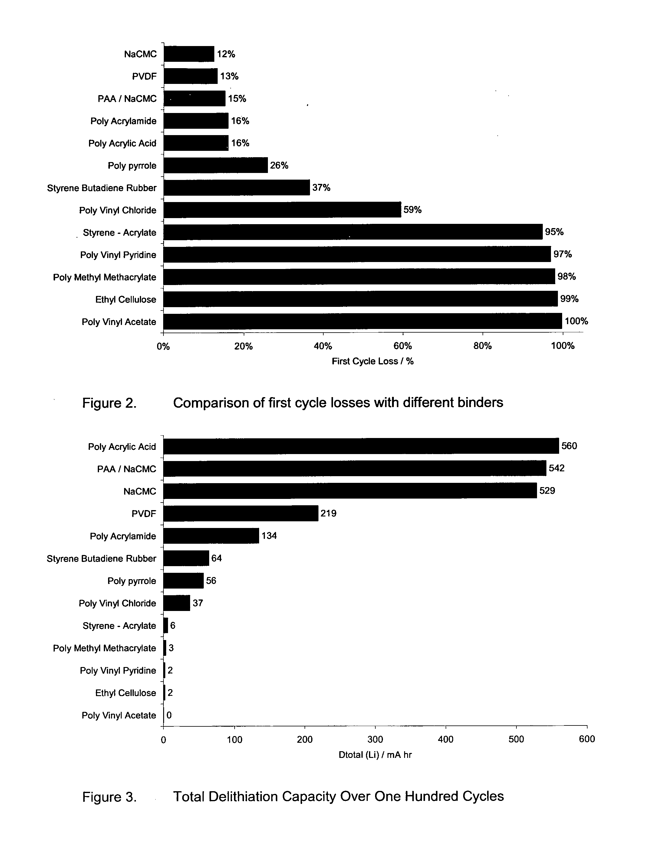
[0050]Using the same cell structure and method of manufacture as in Example 1, cells with various binders as per Table 2 were formed and tested for FCL. The results of the FCL tests for the various binders are shown in the bar chart of FIG. 2. It should be noted that Table 2 includes a wider range of experiments including the different composition ratios such as 74:13:13 whereas FIG. 2 is based on a standard formulation of 80:8:12.

example 3

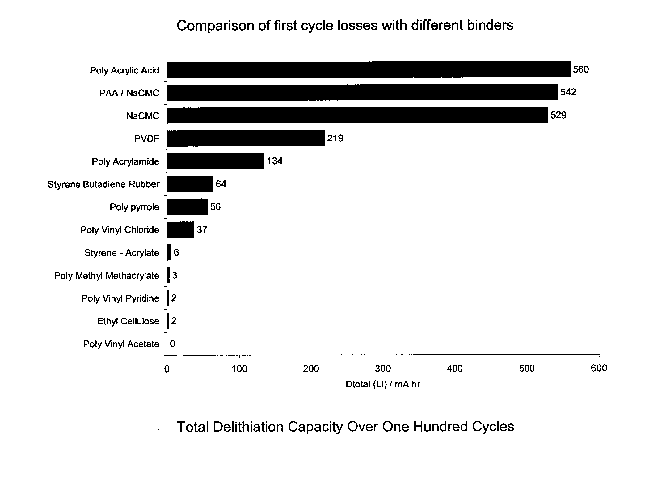
[0051]Using the same cell structure and method of manufacture as in Example 1, cells with various binders were formed as per Table 2 and tested to find the effect of the anode binder on the cycling capacity and the results are shown in the bar chart of FIG. 3. FIG. 3 shows the total delithiation capacity for silicon powder composite electrodes with a lithium metal counter electrode. Delithiation capacity is the amount of lithium capacity in mA hr from the test sample cells associated with the electrochemical step equivalent to the discharge in a real Li-ion cell (i.e. where lithium is removed from the silicon material) The total delithiation capacity is the cumulative amount of capacity from the all the cycles up to the point where the test cell was deemed to have failed.

[0052]Lithium metal electrodes have a limited cycle life, because of the porous and non-uniform deposits that form when lithium is plated back on to the anode during recharging. Typically, the total amount of capaci...


PUM

PropertyMeasurementUnit
Fractionaaaaaaaaaa
Fractionaaaaaaaaaa
Fractionaaaaaaaaaa

Abstract

An electrode for lithium ion recharged battery cell includes current collectors, a cathode layer, a separator and a cohesive anode mass. The cohesive anode mass includes silicon as an active material and a polymeric binder. The polymeric binder is a homo-polymer or copolymer of one or more monomers selected from the group consisting of acrylic acid, 3-butenoic acid, 2-methacrylic acid, 2-pentenoic acid, 2,3-dimethylacrylic acid, 3,3-dymethylacrylic acid, trans-butenedioc acid, cis-butenedioc acid and itaconic acid and optionally an alkali metal salt thereof. The silicon can include 20 to 100% of the active material in the cohesive mass. The binder is mixed with the silicon to form the cohesive mass that adheres to the current collector and maintains the cohesive mass in electrical contact with the current collector.

Description

TECHNICAL FIELD[0001]The invention relates to lithium ion rechargeable battery cells and especially to a binder for use in such cells.BACKGROUND ART[0002]Lithium-ion rechargeable battery cells currently use a carbon / graphite-based anode. The basic composition of a conventional lithium-ion rechargeable battery cell including a graphite-based anode electrode is shown in FIG. 1. A battery may include a single cell but may also include more than one cell.[0003]The battery cell generally comprises a copper current collector 10 for the anode and an aluminium current collector 12 for the cathode, which are externally connectable to a load or to a recharging source as appropriate. It should be noted that the terms “anode” and “cathode” are used in the present specification as those terms are understood in the context of batteries placed across a load, i.e. the term “anode” denotes the negative pole and the term “cathode” the positive pole of the battery. A graphite-based composite anode lay...

Claims


Application Information

Patent Timeline
IPC IPC(8): H01M4/62
CPCH01M4/134H01M4/38H01M4/621Y10T29/49115H01M10/052Y02E60/122H01M4/622H01M4/386Y02E60/10Y02P70/50C08K3/34C08L33/04H01M4/62H01M10/0525
Inventor LOVERIDGE, MELANIE J.LAIN, MICHAEL JONATHANKRONFLI, ESAM
Owner SK ON CO LTD
Why Eureka
Try Eureka