Full expansion internal combustion engine

Inactive Publication Date: 2012-07-12
TAYLOR PATENT HLDG CO LLC
View PDF10 Cites 8 Cited by
  • Summary
  • Abstract
  • Description
  • Claims
  • Application Information

AI Technical Summary

Benefits of technology

[0041]Another aspect of the present invention is the ability to use a wide variety of fuels, including gasoline including low cost, low octane fuels, diesel, alcohol, kerosene, jet-A, and biodiesel, separately, intermittently, or mixed togeth

Problems solved by technology

The airflow and engine power output is controlled by an airflow valve that is closed down as the engine power is reduced, which causes high pressure losses in the intake manifold, especially at low power conditions.
Without the high turbulence levels that can be generated by swirl flow, the mixture is not perfect and the exhaust will contain some undesirable unburned hydrocarbon and carbon monoxide emissions.
The high flame temperatures generated by the stoichiometric fuel-air ratios at all operating conditions also cause high levels of nitrogen oxide emissions and high heat transfer losses from the cylinder.
Also, the compression ratio of the conventional Otto cycle IC engine and the associated engine efficiency is limited by the onset of detonation and pre-ignition which can cause severe damage to the engine.
To prevent overheating of the cylinders and piston seizure in this gasoline engine, caused by the high temperatures, an elaborate cooling system is required with high levels of heat energy losses.
Typical conventional four-stroke Otto cycle engines with water cooling passages cast into the engine crankcase and into the cylinder head are very heavy and costly.
The start of vaporization causes a delay period during ignition and the characteristic diesel “knocking” sound as the vapor reaches ignition temperature and causes an abrupt increase in pressure above the piston.
Increasing the compression ratio in a spark-ignition engine where fuel and air are mixed before entry to the cylinder is limited by the need to prevent damaging pre-ignition.
Unlike Otto-cycle engines, incoming air is not throttled and a diesel engine without a governor cannot have a stable idling speed and can easily overspeed, resultin

Method used


Image

  • Full expansion internal combustion engine
  • Full expansion internal combustion engine
  • Full expansion internal combustion engine

Examples


Embodiment Construction

Definitions

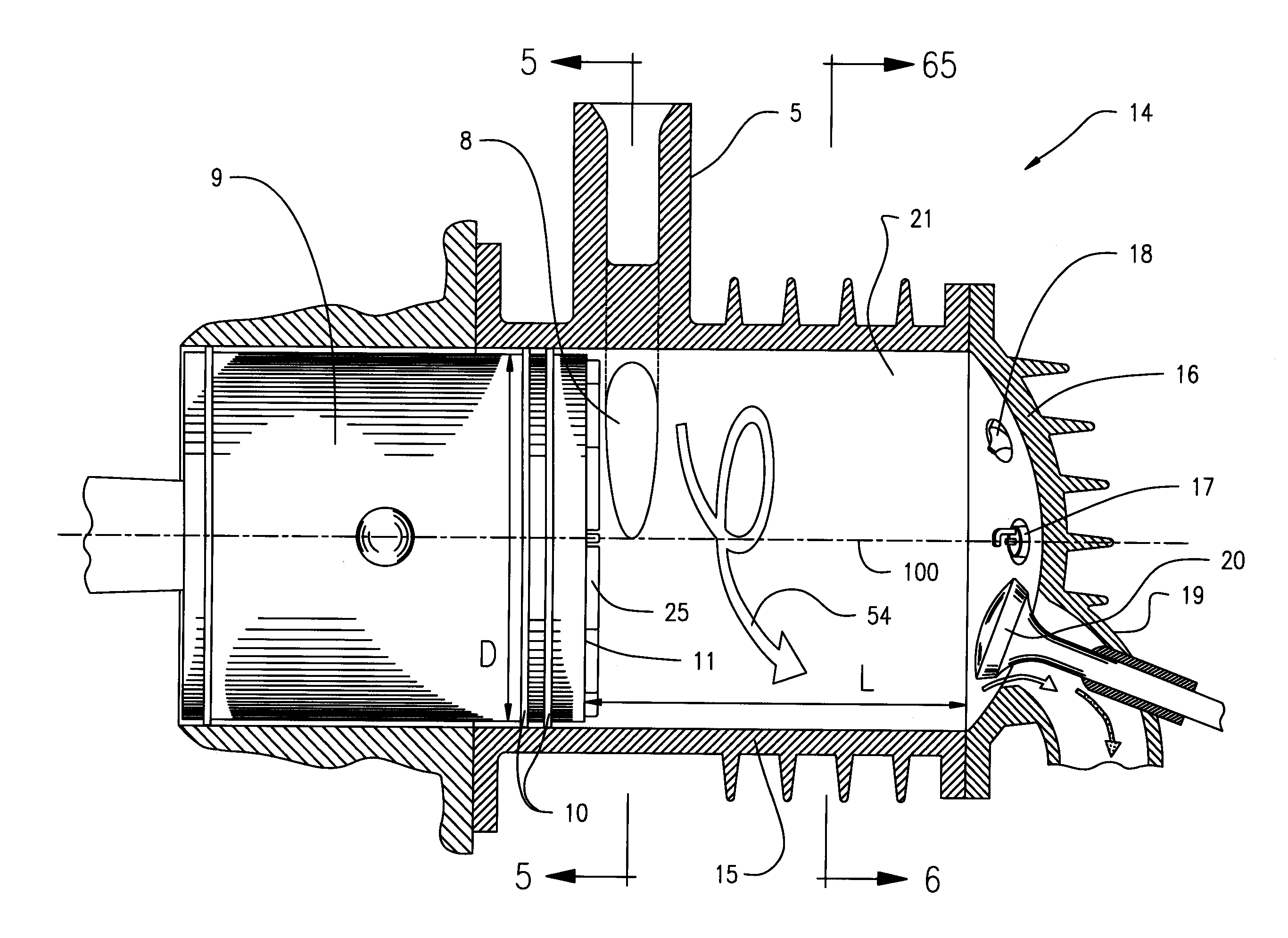
[0060]As used herein, a stratified charge means that the fuel spray from the high pressure injector has a spray pattern that is fuel rich in the center of the spray where the spark ignitor can ignite rich fuel-air ratios and very lean fuel-air ratios.

[0061]As used herein, a spark means includes a means for igniting a fuel-air mixture in a cylinder for combustion, and can include a spark plug, a flame, a heated tube, a laser, and a magneto.

[0062]As used herein, combustion delay time is defined as the time interval between the injection of the fuel and the completion of the temperature rise due to combustion of the fuel.

[0063]As used herein, scavenge efficiency is defined as the percent of fresh air in the cylinder volume when the exhaust valve closes with some of the unscavanged burned gases remaining in the cylinder.

[0064]The present invention provides a two-stroke, uniflow, full expansion cylinder(s) in an internal combustion engine that is configured to operate through ...


PUM


Abstract

A two-stroke, uniflow, full expansion internal combustion (IC) engine having cylinders that include a cylinder wall and a cylinder head having an exhaust port with exhaust valve, a fuel injector, and a spark means in the cylinder head, and a piston mounted in the cylinder for reciprocal stroke movements of compression and power between a top dead center (TDC) position and a bottom dead center (BDC) position. The cylinder has a swirl inlet port passing through the cylinder wall at the bottom of the cylinder that is covered and uncovered in response to the reciprocal movement of the piston. The cylinder is operated through a cycle where the exhaust port is held in an open position for a portion of the compression stroke movement of the piston, to provide a delay in the onset of the compression phase of the cylinder cycle.

Description

CROSS-REFERENCE TO RELATED APPLICATIONS[0001]This application claims the benefit of U.S. provisional patent application 61 / 422,711, filed Dec. 14, 2010, and of U.S. provisional patent application 61 / 542,541, filed Oct. 3, 2011, the disclosures of which are incorporated by reference in their entirety.FIELD OF THE INVENTION[0002]The present invention relates to internal combustion (IC) engines.BACKGROUND OF THE INVENTION[0003]In a conventional Otto cycle internal combustion (IC) engine, the gasoline fuel is injected into the intake manifold to mix with the air and is drawn into the cylinder through the intake valve during the intake stroke. The airflow and engine power output is controlled by an airflow valve that is closed down as the engine power is reduced, which causes high pressure losses in the intake manifold, especially at low power conditions. The fuel flow is metered to produce fuel-air ratios that are very close to stoichiometric for all operating conditions. Without the hi...

Claims


Application Information

Patent Timeline
IPC IPC(8): F02B33/02
CPCF02B25/04Y02T10/146F02B31/04Y02T10/12F02B31/00
Inventor TAYLOR, JACK R.
Owner TAYLOR PATENT HLDG CO LLC
Why Eureka
Try Eureka