Foil trap device with improved heat resistance

a trap device and heat resistance technology, applied in the field of trap devices, can solve the problems of affecting the properties of optical components, deteriorating performance, and ineffectiveness of optical components after a relatively short time, and achieve the effects of reducing thermal diffusivity, good adhesion of carbon materials, and high chemical stability

Active Publication Date: 2012-08-30
USHIO DENKI KK
View PDF2 Cites 9 Cited by
  • Summary
  • Abstract
  • Description
  • Claims
  • Application Information

AI Technical Summary

Benefits of technology

[0007]It is an object of the present invention to provide a foil trap device, in particular for debris mitigation in systems generating EUV and / or soft X-ray radiation, which has a high thermal conductivity, a high thermo-chemical resistance against Sn and a high mechanical stiffness, all at elevated temperatures.
[0015]Composition and properties of the carbon containing phases depend strongly on the preparation conditions. The deposition of the materials can be performed by standard techniques, e.g. by means of physical or especially for diamond-rich phases chemical vapour deposition (PVD and CVD, respectively). In particular the CVD gas phase composition is important. The presence of O or N in the CVD gas phase leads to the formation of non-diamond material and restricts the thermal diffusivity to values below 6×10⁻⁴m2 / s. Isotopically enriched 12C-diamond layers may exhibit a thermal conductivity 20 to 50% higher than that of natural phase-pure diamond and may therefore be advantageous, 13C in the solid reduces the thermal diffusivity by 30%.
[0016]Carbon materials have the advantage to be corrosion resistant to liquid Sn. In particular, at the high temperatures aimed at in this invention, the diamond-containing carbon compounds as well as amorphous diamond films offer higher chemical stability than reached by conventional materials such as copper, steel or molybdenum.
[0017]In case of coating the foils with the proposed carbon material or carbon nanotubes, the base material of the foils is preferably a metallic material as known in the art. In a preferred embodiment, a metal such as W, Ta, Ti or Zr is used as the base material of the foils. These materials have the advantage that metal carbides are synthesized at the interface of the carbon material and the metal by a dedicated vacuum annealing process. This leads to a very good adhesion of the carbon material to the foil and allows choosing an appropriate basic foil material with other properties than in current systems, for example to lower the weight of the foil.

Problems solved by technology

The debris defined in this sense may condense on the optical components whose performance consequently deteriorates, and a status may result, in which the optical component is inefficacious after a relatively short time.
This type of debris is detrimental to the properties, e.g. EUV reflectivity, of the optical components, mainly due to deposition of material on the surface of the optical components.
This leads to a deceleration of particles and material, and in conjunction with e.g. a rotational motion of the foils around the rotational axis, contaminants are collected on the walls of the foils of the trap and thus cannot reach the optical components.
One disadvantage of current foil traps relates to the future perspective of high thermal loads expected in upcoming generations of EUV sources, especially of high-volume production tools for EUV lithography.
It is not straightforward that current and future designs applying current state of the art materials may result in systems being capable of dealing with these high temperatures and fulfill dedicated heat dissipation schemes in order to guarantee a stable and continuous operation and a long lifetime.
Another disadvantage of most current foil traps refers to the thermo-chemical properties of the materials in use.
The problem is that at elevated temperatures every oxide-free metal or alloy will likely react with the still hot Sn delivered from a Sn based plasma light source towards the foil trap.
This chemical reaction, also considered as a form of corrosion by Sn, will deteriorate the properties of the metal based foil trap.
As long as there is no saturation effect of reaction, the foil trap material will dissolve completely and thus lead to the total failure of the debris mitigation.
However, these ceramic materials suffer from the problem to deal with the above mentioned high thermal loads, as they usually exhibit only a very low thermal conductivity.

Method used


Image

  • Foil trap device with improved heat resistance
  • Foil trap device with improved heat resistance
  • Foil trap device with improved heat resistance

Examples


Embodiment Construction

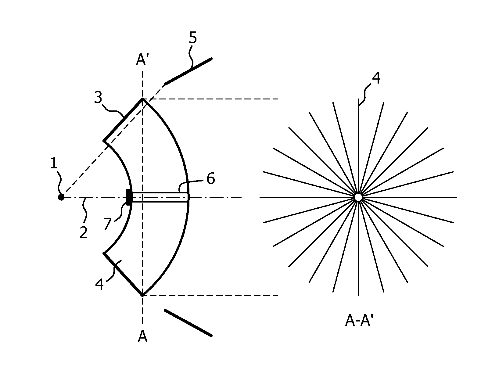
[0023]FIG. 1 shows an exemplary construction of a foil trap according to the present invention in a schematic side view on the left hand side and a front view on the right hand side. The foil trap has a rotating design in which the foils 4 radially extend from a rotation axis 6 to an outer ring 3 serving as a mounting fixture. The foil trap is arranged between the EUV plasma source 1 and an optical component 5 of the EUV system. The optical component 5 may be a collector mirror, for example, as known in the art. The rotation axis 6 of the foil trap is arranged on the optical axis 2 of the EUV system. A heat shield 7 protects the rotation axis 6. EUV radiation emitted from EUV plasma source 1 can pass the foil trap on a straight path between the single foils 4 of the foil trap extending between the entrance side and the exit of the foil trap. By rotating this foil trap around the rotation axis 6, debris particles are trapped by the foils 4 and cannot reach the optical component 5.

[00...


PUM

PropertyMeasurementUnit
thicknessaaaaaaaaaa
thicknessaaaaaaaaaa
thicknessaaaaaaaaaa

Abstract

The present invention relates to a foil trap device for debris mitigation, in particular in an EUV system. The foil trap comprises a plurality of spaced apart foils (4) extending from an entrance side towards an exit side of the foil trap, said foils (4) being arranged to allow a straight pass of radiation between the entrance side and the exit side. The foils (4) are coated at least at entrance side edges with a layer (8, 11) of a carbon material containing a fraction of at least 60% of sp3-hybridized carbon atoms, or with a layer (8, 11) of carbon nanotubes. As an alternative, the foils (4) are made of a bulk carbon material of the above composition. The proposed foil trap offers the combination of a high thermal conductivity, a high thermo-chemical resistance against Sn and other liquid metals and a high mechanical stiffness.

Description

FIELD AND BACKGROUND OF THE INVENTION[0001]The present invention relates to a foil trap device for debris mitigation comprising a plurality of spaced apart foils extending from an entrance side towards an exit side of the foil trap device, said foils being arranged to allow a straight pass of radiation between the entrance side and the exit side of the foil trap device.[0002]In systems with extreme ultraviolet (EUV) and / or soft X-ray radiation optical components such as mirrors or filters are in use which are arranged close to the high power light source. Both, optical components and light source, are in vacuum or least at a very low pressure level (typically 1 to 100 Pa) in order to minimize the absorption of the target radiation to be exploited. The present invention in particular relates to such EUV lithography systems.[0003]In general, the light source, e.g. a pulsed plasma light source, is not merely emitting photons but also producing undesired material, so called debris, such...

Claims


Application Information

Patent Timeline
Patent Type & Authority Applications(United States)
IPC IPC(8): B01D49/00B82Y30/00
CPCG03F7/70166G03F7/70883Y10S977/778G03F7/70958G03F7/70983G03F7/70916
Inventor METZMACHER, CHRISTOFSCHAAF, MICHAELBACHMANN, PETER KLAUS
Owner USHIO DENKI KK
Why Eureka
Try Eureka