Gas tungsten arc welding using flux coated electrodes

a flux coated electrode and gas tungsten technology, applied in the field of gas tungsten arc welding using flux coated electrodes, can solve the problems of inability to protect the backside of the weld pool, no universal solution for reactive materials in general and in particular for nickel based alloys,

Inactive Publication Date: 2012-09-06
SIEMENS ENERGY INC
View PDF10 Cites 20 Cited by
  • Summary
  • Abstract
  • Description
  • Claims
  • Application Information

AI Technical Summary

Benefits of technology

[0011]A shielding gas may be applied to the welding location concurrently with providing an electrical current to the non-consumable tungsten electrode, wherein the shielding gas stabilizes the welding arc and protects the non-consumable tungsten electrode from oxidation.

Problems solved by technology

When applying welds to certain welding locations, access to for protection of the backside of the weld pool may be impractical due to complexity of system design, access limitations and increased procedure costs and schedule.
While methods to successfully produce sound root passes in 300 series stainless steel applications have been developed, no universal solution for reactive materials in general and in particular for Nickel based alloys is available.

Method used


Image

  • Gas tungsten arc welding using flux coated electrodes
  • Gas tungsten arc welding using flux coated electrodes
  • Gas tungsten arc welding using flux coated electrodes

Examples


Embodiment Construction

[0028]In the following detailed description of the preferred embodiments, reference is made to the accompanying drawings that form a part hereof, and in which is shown by way of illustration, and not by way of limitation, specific preferred embodiments in which the invention may be practiced. It is to be understood that other embodiments may be utilized and that changes may be made without departing from the spirit and scope of the present invention.

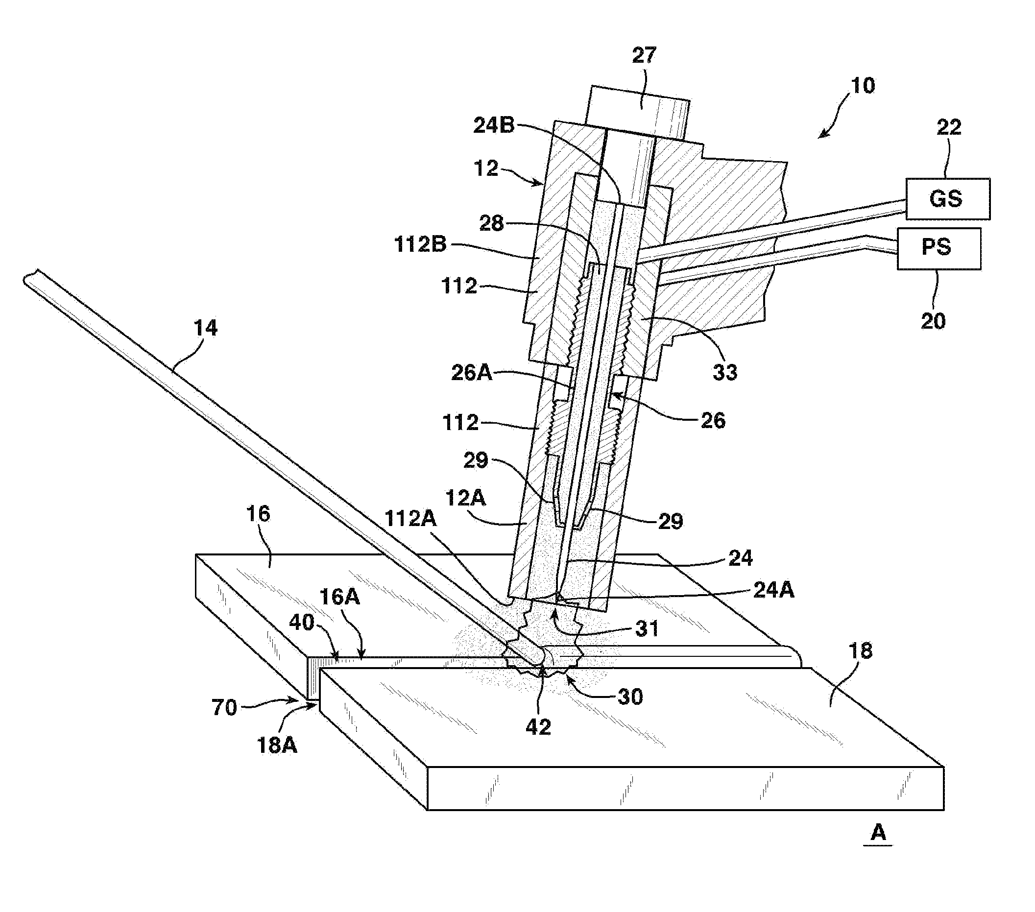
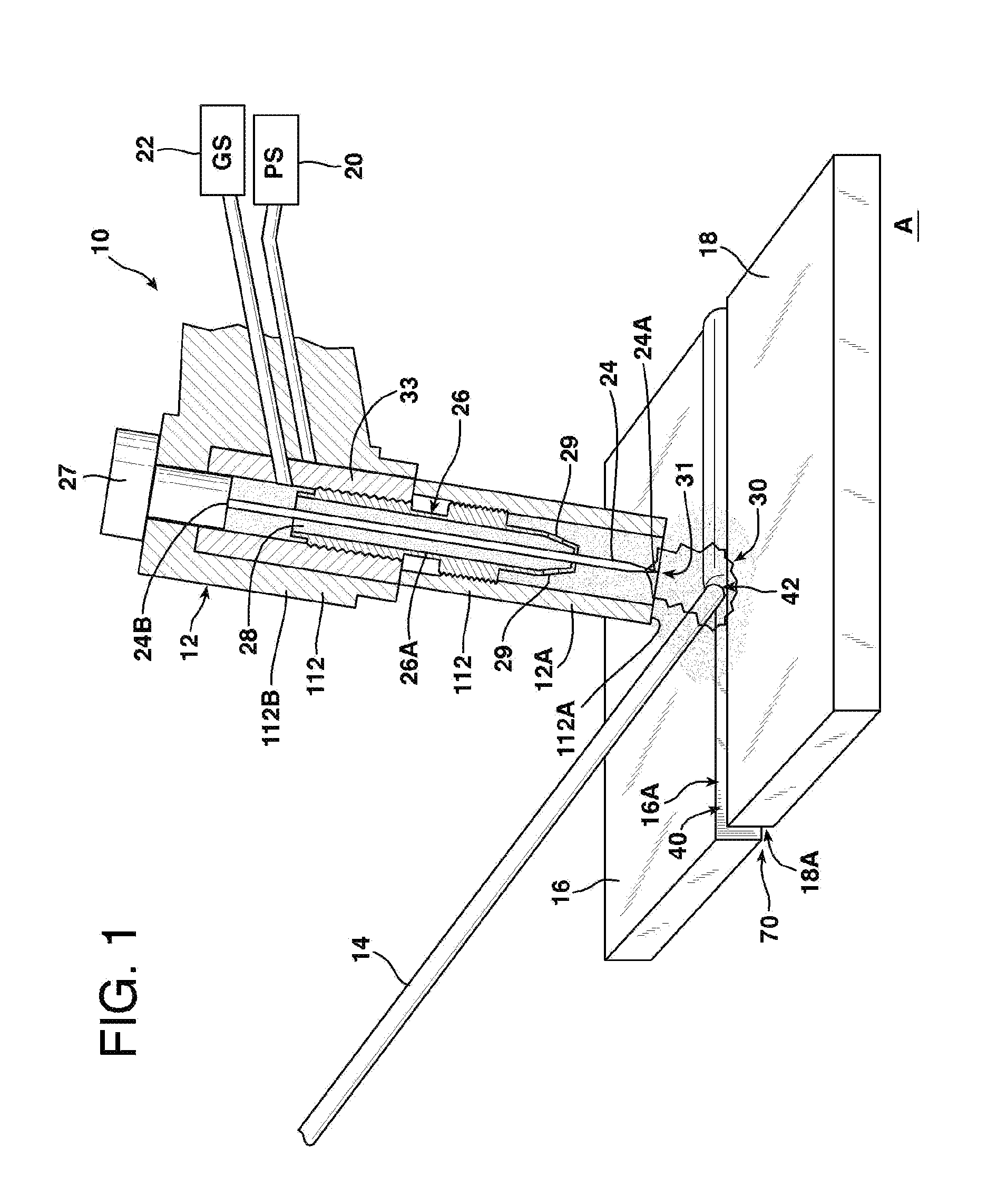
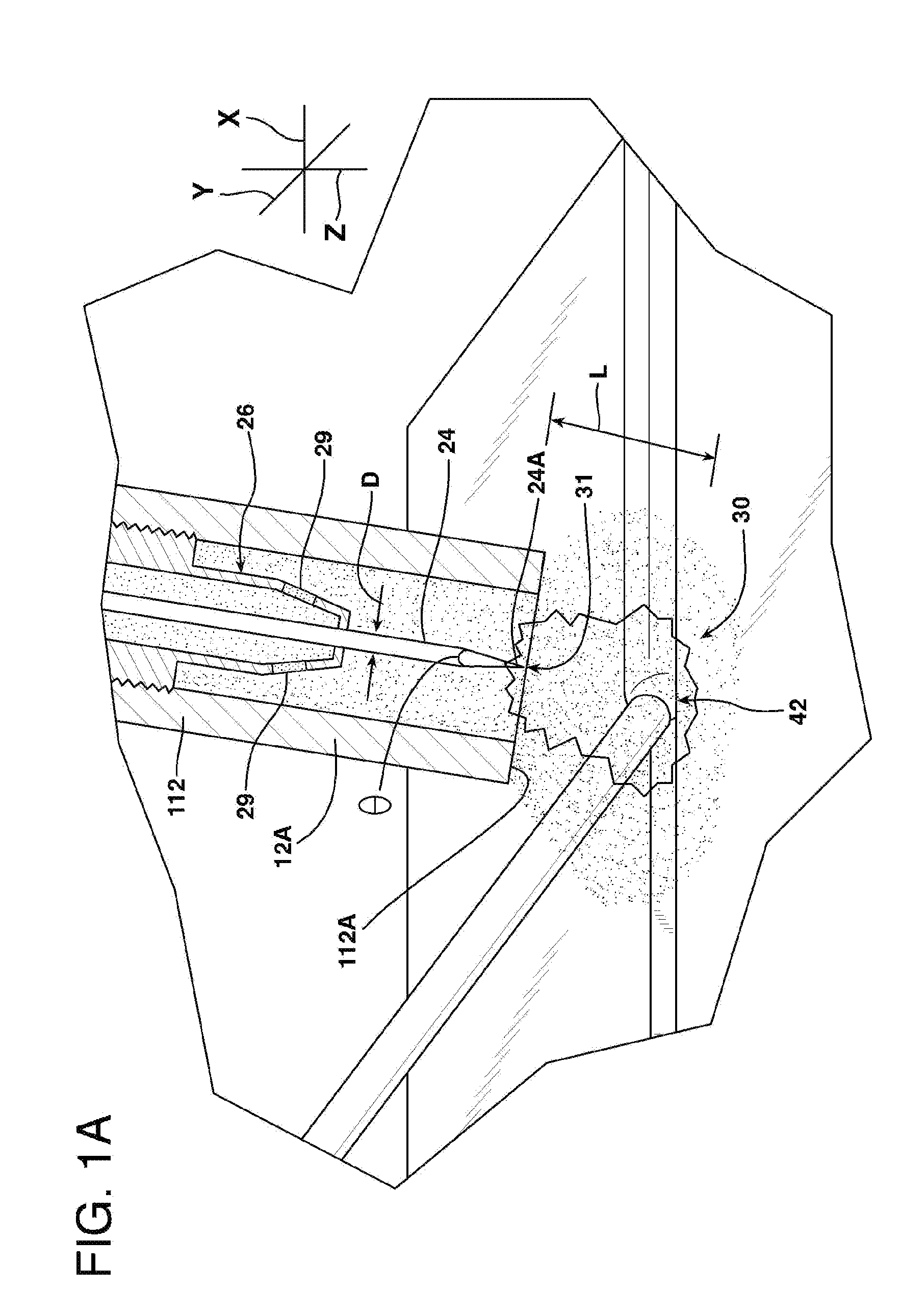
[0029]Referring to FIG. 1, a gas tungsten arc welding (GTAW) system 10 according to an embodiment of the present invention is illustrated. The system 10 illustrated in FIG. 1 is used in connection with a GTAW procedure of the present invention and includes a welding torch 12 and a filler element 14. Also illustrated in FIG. 1 are first and second components 16, 18 to be joined together using the GTAW procedure.

[0030]The welding torch 12 illustrated in FIG. 1 is a manually operated torch 12, but mechanically operated torches could be used...


PUM

PropertyMeasurementUnit
lengthaaaaaaaaaa
lengthaaaaaaaaaa
lengthaaaaaaaaaa

Abstract

A method of applying a weld using a gas tungsten arc welding procedure. A filler element is provided to a welding location. The filler element includes a first material used during formation of a weld, and a second material that is capable of producing a slag upon melting thereof. A welding arc provides heat that melts portions of first and second components and the filler element proximate to the welding location to form a weld pool. The second material melts and forms a slag, which flows to an outer surface of the weld pool and shields the weld pool from exposure to reactive elements in the atmosphere. Upon cooling of the weld pool, the weld pool solidifies to form a weld between the first component and the second component.

Description

FIELD OF THE INVENTION[0001]The present invention relates to welding, and, more particularly, to gas tungsten arc welding using a flux coated electrode to produce a shielding slag that shields the weld pool from reactive elements in the atmosphere and improves wetting.BACKGROUND OF THE INVENTION[0002]Open root welding procedures may be used to apply welds between stainless steel or nickel based alloy components in gas turbine engine exhaust sections. Procedures for open root welding often utilize a shielding material, i.e., a backing or shielding plate or a backing or shielding gas, e.g., argon, during first weld passes, typically referred to as root and hot passes, to shield the backside of the weld pool and weld root from atmospheric contamination. When applying welds to certain welding locations, access to for protection of the backside of the weld pool may be impractical due to complexity of system design, access limitations and increased procedure costs and schedule.[0003]Prior...

Claims


Application Information

Patent Timeline
Patent Type & Authority Applications(United States)
IPC IPC(8): B23K9/16
CPCB23K9/167B23K35/0261B23K35/222F01D5/28B23K35/3046B23K2201/001B23K35/3033B23K2101/001B23K35/02F01D5/30
Inventor IORDACHE, LUCIANTIMOTIN, OVIDIUSCHUMACHER, CHRIS E.SCHUMACHER, PATRICKBRUCK, GERALD J.
Owner SIEMENS ENERGY INC
Why Eureka
Try Eureka