Method for Drying Thin Films in an Energy Efficient Manner

a technology of energy-efficient drying and thin films, applied in the direction of drying solid materials, drying, drying, etc., can solve the problems of reducing the maximum working temperature of expensive substrates, reducing the drying temperature, and utilizing relatively low temperatures to dry thin films

Active Publication Date: 2012-10-11
NCC NANO LLC
View PDF8 Cites 9 Cited by
  • Summary
  • Abstract
  • Description
  • Claims
  • Application Information

AI Technical Summary

Benefits of technology

[0008]In accordance with a preferred embodiment of the present invention, a thin film stack is thermally processed by conveying the thin film stack past a flashlamp during which the thin film stack is irradiated with a composite light pulse from the flashlamp. The composite light pulse is composed of multiple micropulses. The time duration of the composite light pulse is shorter than a total thermal equilibration time of the thin film stack. In addition, when the thin film stack is being conveyed past the flashlamp, the thin film stack should move less than 10% of the length of the irradiating area in the conveyance direction during the delivery of the composite light pulse.

Problems solved by technology

However, inexpensive substrates tend to have lower maximum working temperatures than their expensive counterparts such that only relatively low temperatures can be utilized to dry thin films located on inexpensive substrates.
Hence, a small reduction in the drying temperature will require a significantly longer drying time and more energy, which translates to a more costly drying operation.

Method used


Image

  • Method for Drying Thin Films in an Energy Efficient Manner
  • Method for Drying Thin Films in an Energy Efficient Manner
  • Method for Drying Thin Films in an Energy Efficient Manner

Examples


example 1

Drying and Sintering of Nano-Silver Ink on PET

[0055]Two samples of nano-silver ink on PET were prepared, each sample being a 1 micron thick of nano-silver thin film printed on a 150 micron thick PET substrate. A first sample was dried in an oven at 150° C. for 5 minutes to drive off solvent and exposed to a single light pulse of 1 ms in duration at 1.6 kW / cm2 at a webspeed of 10 m / min with an overlap factor of 4 depositing 1.6 J / cm2 of energy with each delivery of single light pulse for a total of 6.4 J / cm2 energy deposited onto the substrate to sinter the silver.

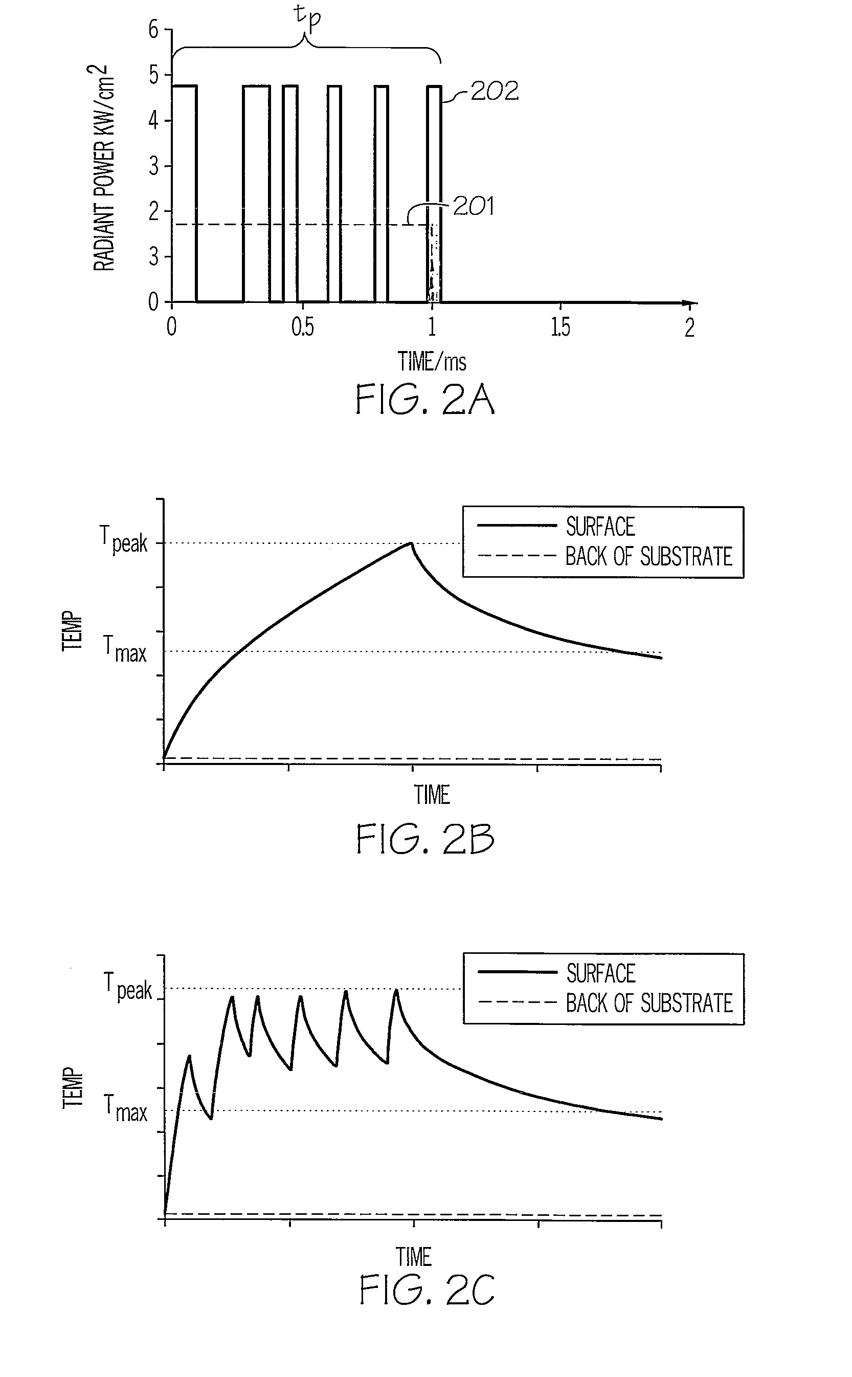
[0056]Without being dried in the oven, the second sample was exposed to a 1 ms long composite light pulse comprised of 6 different micropulses of differing pulse lengths and delays, and the timing (in μs) of the composite light pulse is shown in Table III.

TABLE IIITurn onTurn off01002893744394746046447898299991,037

[0057]The intensity of the light pulses was increased to 4.7 kW / cm2 so that the total amount of energy deposite...

example 2

Multi-Temperature Zone Processing Accounting for Solvent Evaporation

[0062]The tunability of the pulse profile is particularly useful for drying thin films where multiple distinct processes can be performed in a single pass. In short, a thin film that contains solvent cannot be heated as rapidly as one which is already dried. That is, when solvent is in the thin film, a high power will rapidly expand the solvent and “explode” the thin film, resulting in a cohesive failure. Ideally, one desires to first remove the solvent at a lower power until it is removed followed by a higher power exposure to perform additional thermal processing such as sintering. FIG. 2d shows a representative thermal response profile of the film and substrate of example 1 from a composite pulse in which the first portion of the pulse maintains the temperature at the surface of the thin film at about 700° C. for the first 1.2 ms, followed by a higher power exposure in order to maintain the thin film's temperatur...

example 3

Prevention of Cohesive Failure in a Thin Film by Modulation of Gas Generation

[0064]An aqueous copper precursor ink was formulated comprising 10.0% wt. copper (II) oxide, 4.5% wt. copper (II) acetate in a base containing ethylene glycol and glycerol. Traces were printed onto a 125 micron thick PET sheet using an Epson Stylus C88 ink jet printer. Upon curing with a flashlamp, the copper oxide and copper acetate are reduced by the ethylene glycol and glycerol to form a film of conductive copper metal. The reduction reaction generates a moderate amount of gas.

[0065]The printed film was cured using the method and apparatus of the present invention with the following conditions: voltage 250 V, composite light pulse duration=˜1,050 microseconds, 4 micropulses with a duty cycle of 0.6 (i.e., each micropulse was 175 microsecond long with a delay of 117 μs between pulses), overlap factor=3, web speed=6.4 m / min. The sample yield was 100% with an average sheet resistance of 3.7 Ω / □.

[0066]When t...


PUM

PropertyMeasurementUnit
temperatureaaaaaaaaaa
total timeaaaaaaaaaa
thermal equilibration timeaaaaaaaaaa

Abstract

A method for drying a thin film stack having a thin film located on a substrate is disclosed. The thin film stack is conveyed past a flashlamp during which the thin film stack is irradiated with a composite light pulse from the flashlamp. The composite light pulse is composed of multiple micropulses. The time duration of the composite light pulse is shorter than a total thermal equilibration time of the thin film stack. In addition, when the thin film stack is being conveyed past the flashlamp, the thin film stack should move less than 10% of the length of the irradiating area in the conveyance direction during the delivery of the composite light pulse.

Description

PRIORITY CLAIM[0001]The present application is a continuation-in-part of U.S. patent application Ser. No. 13 / 082,469, filed on Apr. 8, 2011, the contents of which are incorporated herein by reference.BACKGROUND OF THE INVENTION[0002]1. Technical Field[0003]The present invention relates to thermally processing thin films in general, and, in particular, to a method for drying thin films by using light pulses from a flashlamp.[0004]2. Description of Related Art[0005]When it comes to choosing substrates for supporting thin films, it is generally more preferable to employ inexpensive substrates, such as polyethylene terephthalate (PET), polycarbonate, cellulose, etc., over expensive substrates, such as silicones, fluorocarbons, ceramic, glass, etc., due to cost reasons. However, inexpensive substrates tend to have lower maximum working temperatures than their expensive counterparts such that only relatively low temperatures can be utilized to dry thin films located on inexpensive substra...

Claims


Application Information

Patent Timeline
Patent Type & Authority Applications(United States)
IPC IPC(8): F26B7/00
CPCB29B13/023B29B13/06H05K3/1283B29C35/0805B29C35/10B29B13/08
Inventor SCHRODER, KURT A.RAWSON, IAN M.MCCOOL, STEVEN C.EDD, ANDREW E.DASS, RONALD I.
Owner NCC NANO LLC
Why Eureka
Try Eureka