Ion source and repeller structure

a technology of ion source and structure, applied in the field of ion source, can solve the problems of structural complexity the size of the ion source is increased, and the efficiency of the reflected electron is reduced, so as to improve the efficiency of reflected electrons emitted, improve the efficiency of sputtering surface area, and simplify the effect of the mounting structur

Inactive Publication Date: 2012-10-11
NISSIN ION EQUIP CO LTD
View PDF4 Cites 37 Cited by
  • Summary
  • Abstract
  • Description
  • Claims
  • Application Information

AI Technical Summary

Benefits of technology

[0030]The present invention configured as above makes it possible to generate a gallium ion-containing ion beam without using an organic metal gas, and improve efficiency of reflecting electrons emitted fro...

Problems solved by technology

However, considering that the repeller is disposed within the plasma generating chamber, i.e., a limited space, there is a restriction on the size of the repeller.
Thus, the size of the target member to be housed in the repeller will be restricted, which poses a problem of difficulty in increasing an area of a sputterable surface (a sputterable surface area) of the target member.
The above structure in which the repeller is disposed around the outer peripheral surface of the target member has another problem of an increase in size of the repeller.
This results in structural complexity of the repeller, and is likely to cause increases in material cost and machining cost when the repeller is fabricated from a single member by cutting.
This causes problems of deterioration in electron reflection efficiency and thus deterioration in ...

Method used


Image

  • Ion source and repeller structure
  • Ion source and repeller structure
  • Ion source and repeller structure

Examples


Embodiment Construction

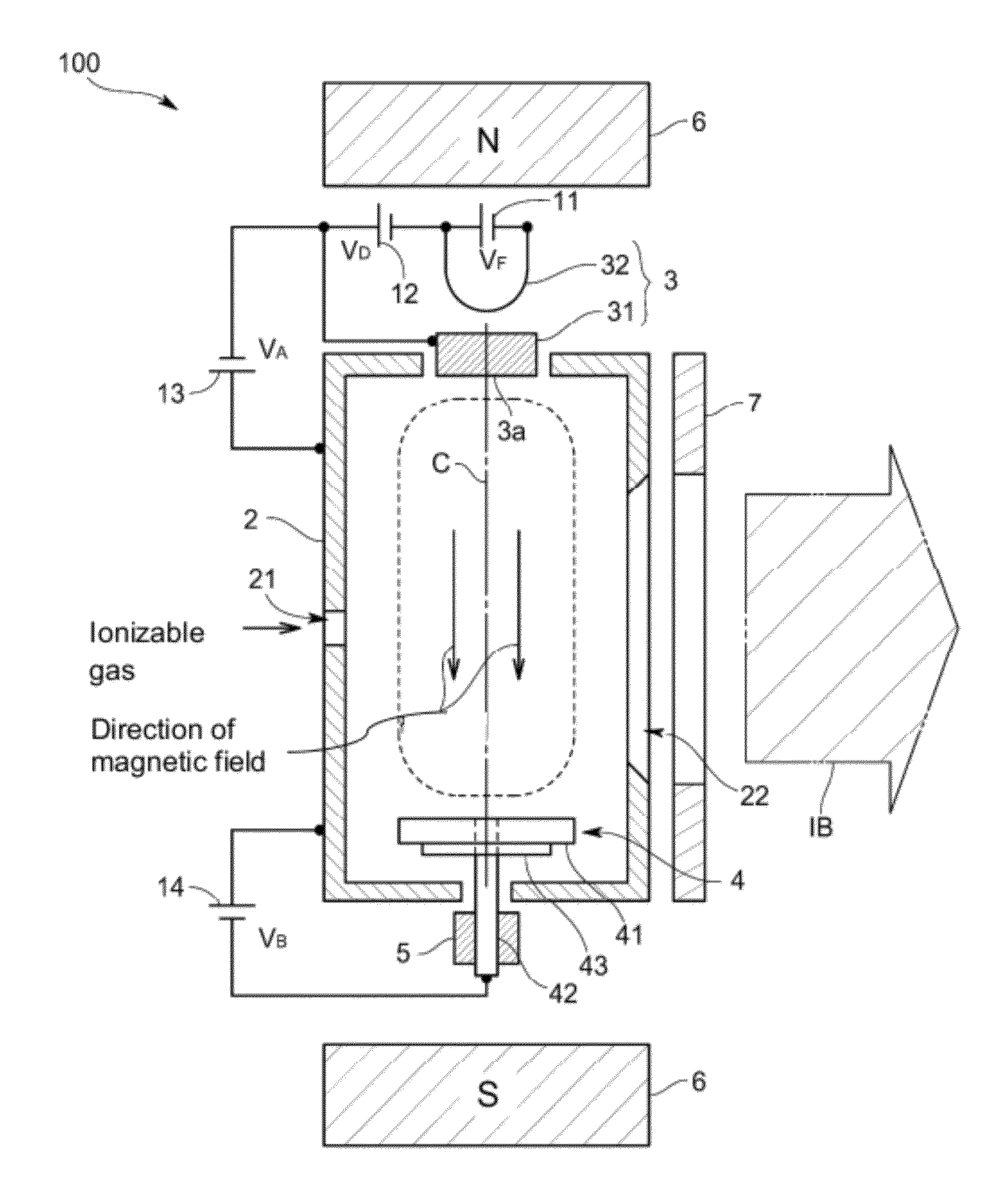
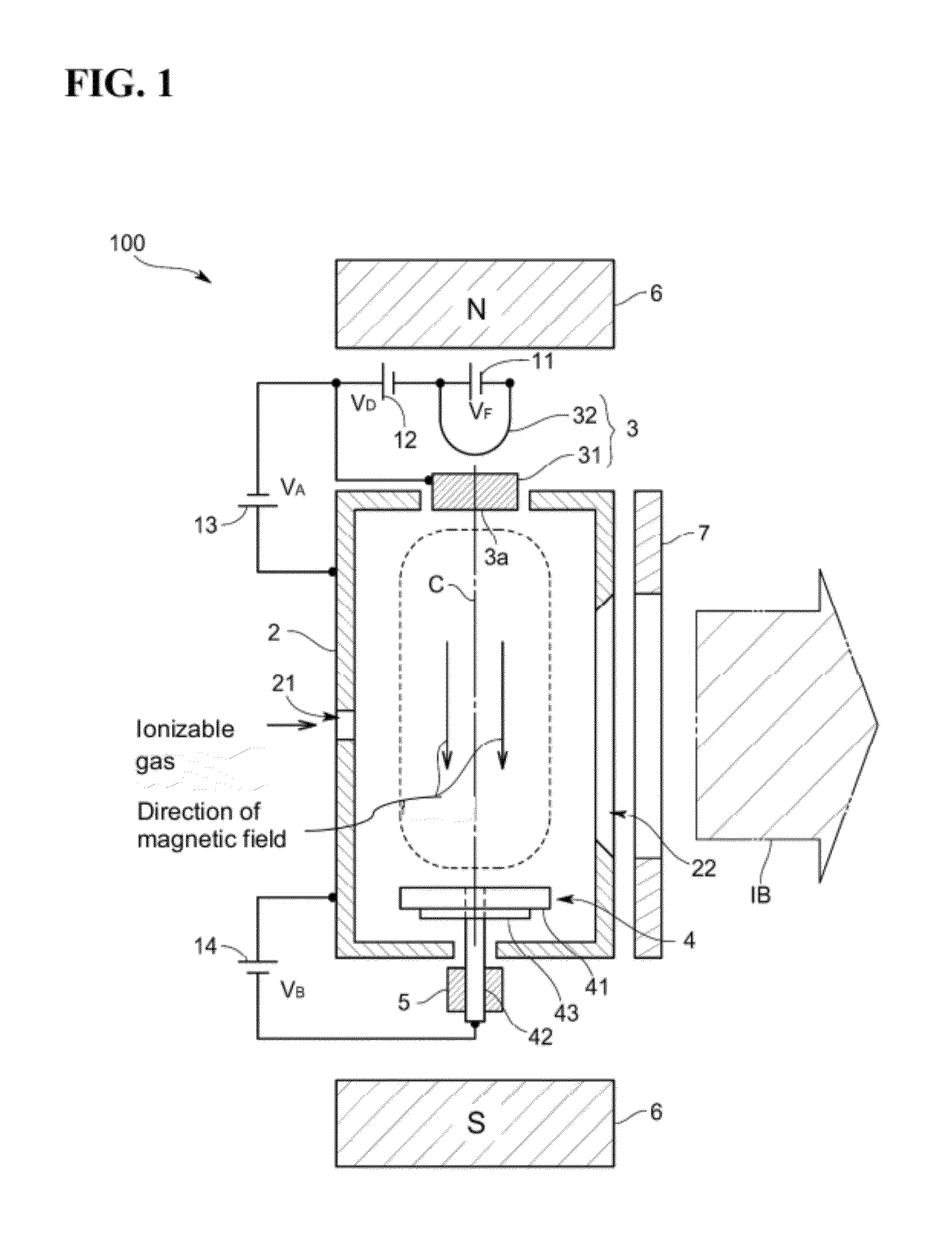
[0043]With reference to the drawings, the present invention will now be described based on an ion source according to an embodiment thereof.

[0044]As illustrated in FIG. 1, an ion source 100 according to one embodiment of the present invention is designed to generate an ion beam IB containing gallium ions, and equipped with a plasma generating chamber 2, a hot cathode 3 provided in the plasma generating chamber 2, and a repeller structure 4 disposed in opposed relation to the hot cathode 3 within the plasma generating chamber 2.

[0045]The above components 2 to 4 will be described in detail below.

[0046]The plasma generating chamber 2 configured to serve as both a container (e.g., a rectangular parallelepiped-shaped container) for generating therein a plasma, and an anode for arc discharge, and provided with a gas inlet port 21 for introducing an ionizable gas serving as a source gas thereinto, and an ion extraction port 22 for extracting internally generated gallium ions to the outside...


PUM


Abstract

A repeller structure comprises a target member configured to be sputtered by a plasma to emit given ions, and provided with a through-hole penetrating between a sputterable surface and a reverse surface thereof, and a repeller body which supports the target member while being inserted in the through-hole of the target member, and has a repeller surface exposed on the side of the sputterable surface through the through-hole. The target member is made of a material selected from the group consisting of gallium oxide, gallium nitride, gallium phosphide, gallium arsenide and gallium fluoride.

Description

BACKGROUND OF THE INVENTION[0001]1. Field of the Invention[0002]The present invention relates to an ion source, and more particularly to a repeller structure disposed in opposed relation to an electron emitting cathode within a plasma generating chamber of an ion source to reflect the electrons toward the cathode.[0003]2. Description of the Background Art[0004]In recent years, it has been studied to, in a plasma generating chamber of an ion source, ionize a source gas by a cathode to generate a plasma, and sputter a target material by the generated plasma to allow desired ion species to be contained in an ion beam.[0005]Specifically, the target material is provided at a distal end of a repeller and held in a replaceable manner so as to allow stable generation of ion species, as disclosed in the following Patent Document 1. A detailed structure therefor comprises a tubular repeller, and a target member (slug) which is housed in a distal end of the repeller. The repeller has a stepped...

Claims


Application Information

Patent Timeline
IPC IPC(8): B05B5/00
CPCH01J37/08H01J27/205H01J2237/081H01J37/3171H01J27/02
Inventor TANJO, MASAYASU
Owner NISSIN ION EQUIP CO LTD
Why Eureka
Try Eureka