
Organic electroluminescent element and novel alcohol-soluble phosphorescent material

a technology of organic electroluminescent elements and phosphorescent materials, which is applied in the direction of organic chemistry, organic semiconductor devices, thermoelectric devices, etc., can solve the problems of different solubility of lamination, reduce productivity, etc., and achieve excellent electron-injection properties, durability and luminescent efficiency, and high quantum yield.

Inactive Publication Date: 2012-10-18
DAIDEN CO LTD
View PDF8 Cites 41 Cited by
  • Summary
  • Abstract
  • Description
  • Claims
  • Application Information

AI Technical Summary

Benefits of technology

[0012]In terms of improving the properties by using materials optimized for functions of the electron transfer, the hole transfer and the luminescent, it is preferred to increase the number of layers to be laminated between the anode and the cathode by separating each function. However, increasing number of layers to be laminated may lead to increase in number of processes and tact time required for the production and performance degradation due to the etching of the underlying layer by the solvent.
[0035]The present invention provides an organic electroluminescent element having an emissive layer that may be formed by wet process in the fabrication of the organic electroluminescence device with multi-layer structure and has excellent electron-injection property, electron-transfer property, durability and luminescent efficiency and a novel alcohol-soluble organic phosphorescent material that may be preferably applicable to the fabrication of the same. By the use of the alcohol-soluble phosphorescent material of the present invention, the electron transport layer and the laminated low-molecule organic EL element without using expensive vacuum deposition equipment and complicated setting for co-evaporation of the metal and the organic electron transport material. Hence, production cost of the production of the electron transport layer and the laminated low-molecule organic EL element may be reduced as well as the productivity may be enhanced. By the application of the present invention, the organic electroluminescent element that may be produced at high productivity and low cost and is excellent in luminescent efficiency and durability may be provided.

Problems solved by technology

Moreover, production of the electron transport layer and the electron injection layer according to the aforementioned inventions by means of vacuum vapor deposition method requires large-scale facility and has the difficulty in precisely adjusting the deposition rates in the simultaneous deposition of more than two materials, which leads to a decrease in the productivity.
In the former method, while a wide variety of materials may be chosen, removal of an initiator and unreacted material is difficult after the cross linking or the polymerization, which causes the problem in durability.
One of the factors that make the lamination using the different in the solubility of constituent material of each layer difficult is that most conducting polymers and spin-coatable organic semiconductors are soluble in solvents with relatively high solubilizing ability such as toluene, chloroform and tetrahydrofuran.
Therefore, when a spin-coating of a n-type conductive polymer is carried out after forming a hole transport layer of p-type conductive polymer using similar solvents, etching of the underlying hole carrier polymer layer occurs, which makes difficult to form a lamination structure with flat and defect-free p-n interface.
Especially, in an ink-jet process in which solvent is removed by natural drying, strong etching of the hole transport layer and the luminescent layer takes place because the solvent stays longer, which makes the achievement of the sufficient properties for practical purposes very difficult.
However, increasing number of layers to be laminated may lead to increase in number of processes and tact time required for the production and performance degradation due to the etching of the underlying layer by the solvent.

Method used


Image

  • Organic electroluminescent element and novel alcohol-soluble phosphorescent material
  • Organic electroluminescent element and novel alcohol-soluble phosphorescent material
  • Organic electroluminescent element and novel alcohol-soluble phosphorescent material

Examples


examples

[0129]Hereinafter, the examples for confirming the effect of the present invention will be described.

(1) Synthesis of Host Materials

[0130]Among the host materials used (phosphine oxide derivatives: represented by Formula A to Q shown above), what are described in PCT Gazett WO 2005 / 104628 were synthesized according to the described method in the Gazett.

(2) Synthesis of Guest Material

[I] Synthesis of [bis(2-phenylpyridinato-N,C2′)-mono(2-(4-diphenylphosphoryl) pyridinato-N,C2′)]iridium (III) (Ir(ppy)2(pdppy))

(I-1) Synthesis of 4-bromophenyldiphenylphosphine oxide (pBrdppo)

[0131]

[0132]To 2.16 g (88.9 mmol) of magnesium, 5 mL of THF was added, then a THF solution of 22 g of 1,4-dibromobenzene (93.2 mmol) was added dropwise at 0° C. The mixture was stirred until all magnesium was consumed, then 40 mL of THF was added and the mixture was stirred for 1 hour. The mixture was cooled to 0° C. and 15.7 mL of diphenylphosphoryl chloride (84.5 mmol) was added dropwise. The mixture was stirred o...


PUM

PropertyMeasurementUnit
Fractionaaaaaaaaaa
Fractionaaaaaaaaaa
Fractionaaaaaaaaaa

Abstract

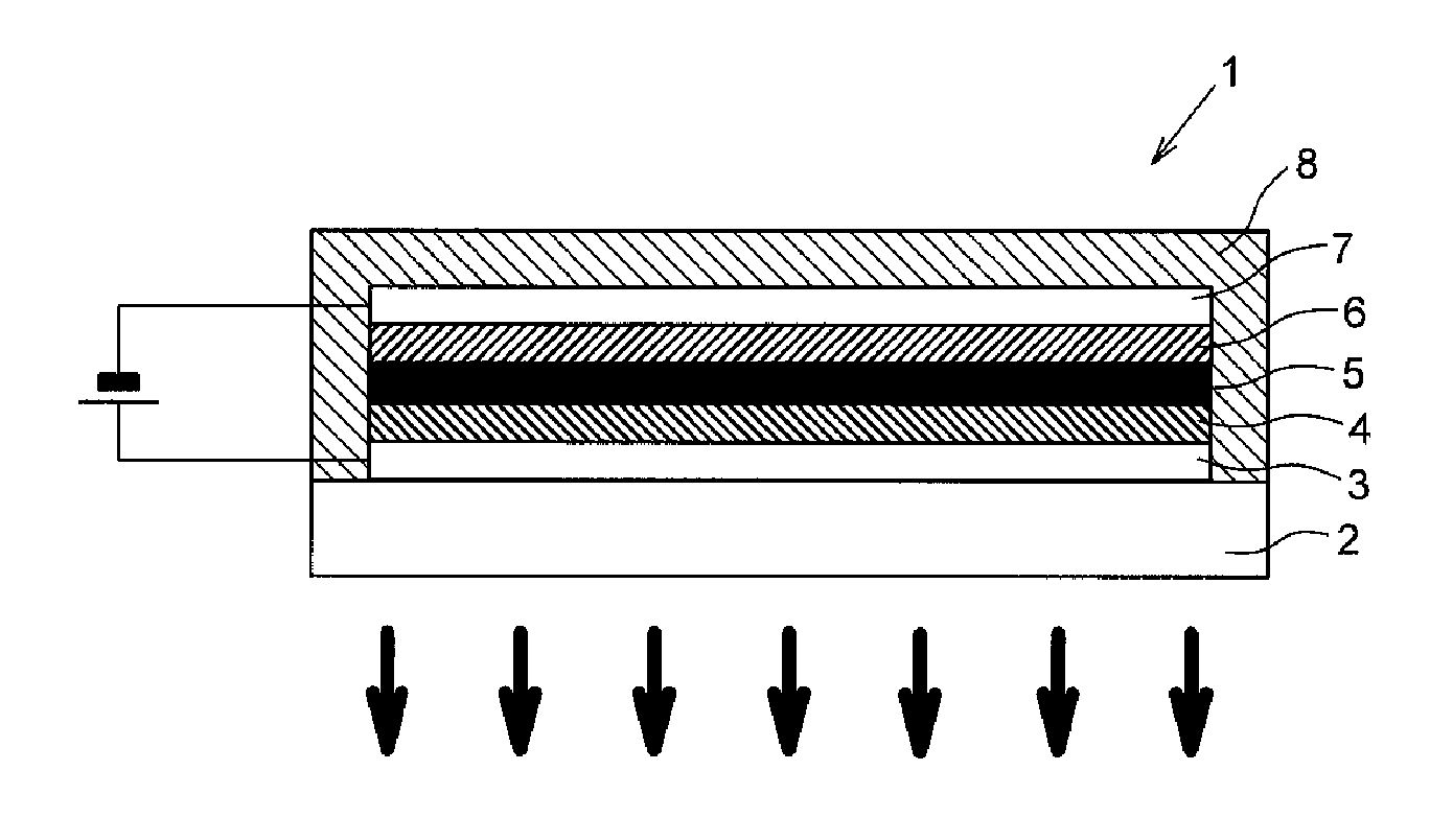
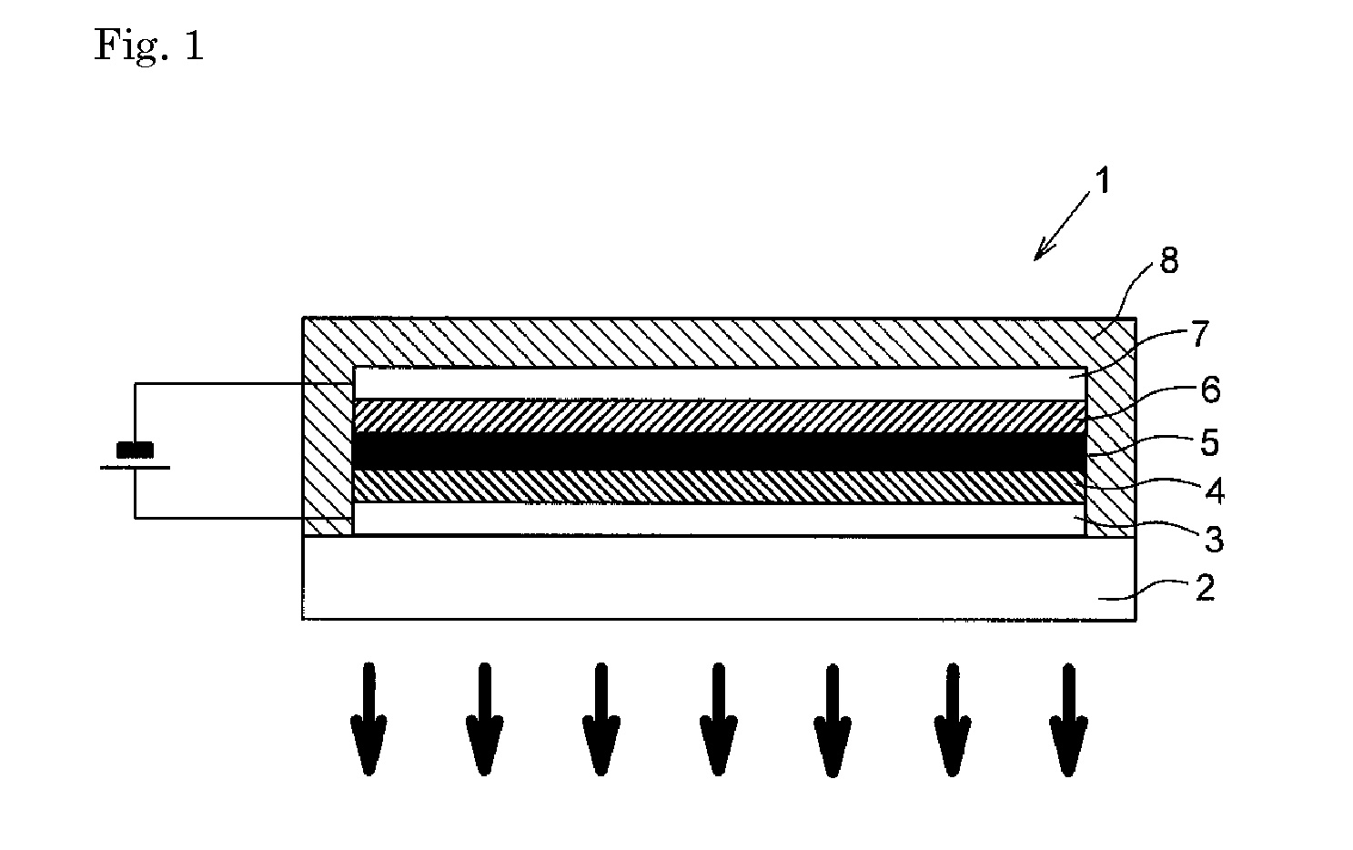
Object of the present invention is to provide an organic electroluminescent element having an emissive layer that may be formed by wet process in the fabrication of the organic electroluminescence device with multi-layer structure and has excellent electron-injection property, electron-transfer property, durability and luminescent efficiency and a novel alcohol-soluble organic phosphorescent material that may be preferably applicable to the fabrication of the same. An organic electroluminescent element 1 has a plurality of laminated organic layers 4, 5, 6 sandwiched between anode 3 and cathode 7. A hole transport layer 5 composed of organic compounds insoluble in alcohol solvent and an emissive layer 6 formed by a wet process so that it contacts with the hole transport layer 5 on the side facing with the cathode 7 contains host materials consisting of one or more phosphine oxide derivatives soluble in alcohol solvent and guest materials soluble in alcohol solvent which can be excited electrically to emit light.

Description

BACKGROUND OF THE INVENTION[0001]1. Field of the Invention[0002]The present invention relates to an organic electroluminescent element and novel alcohol-soluble phosphorescent material. Particularly, the present invention relates to an organic electroluminescent element having an emissive layer that may be formed by wet process in the fabrication of the organic electroluminescence device with multi-layer structure and has excellent electron-injection property, electron-transfer property, durability and luminescent efficiency and to a novel alcohol-soluble organic phosphorescent material that may be preferably applicable to the fabrication of the same.[0003]2. Description of the Related Art[0004]An organic electroluminescent element in which an emissive organic layer (organic electroluminescent layer) is situated between anode and cathode (hereinafter abbreviated as “organic EL element”) has advantages that it may be operated at DC low voltage and has higher luminance and emission ef...

Claims


Application Information

Patent Timeline
IPC IPC(8): H01L51/54C07F17/00
CPCC09K11/06C07F15/0033C09K2211/1014C09K2211/1029C09K2211/1044C09K2211/185H01L51/0003H01L51/0037H01L51/0042H01L51/0085H01L51/5016H01L51/56H01L2251/308H05B33/14C09K2211/1007H10K71/12H10K85/146H10K85/1135H10K85/342H10K50/11H10K2101/10H10K2102/103H10K71/00H10K71/50
Inventor NOTO, MITSUHARUSAKAI, YUMIKAKINOKI, IZUMIGOTO, YASUYUKI
Owner DAIDEN CO LTD
Learn More