Insulated wire

a technology of insulated wires and insulating conductors, which is applied in the direction of insulated conductors, cables, conductors, etc., can solve the problems of low voltage decay due to connection cables, high steep voltage rise, and output pulses due to high-speed switching devices such as igbt, and achieve excellent partial discharge resistance and dielectric breakdown resistance. , the effect of high dielectric breakdown resistan

Inactive Publication Date: 2012-11-15
FURUKAWA ELECTRIC CO LTD +1
View PDF14 Cites 30 Cited by
  • Summary
  • Abstract
  • Description
  • Claims
  • Application Information

AI Technical Summary

Benefits of technology

[0016]According to the present invention, an insulated wire can be provided, which is high in a dielectric breakdown resistance even if insulating resin coatings are laminated, because the interlayer adhesiveness is excellent, and which is excellent in a partial discharge resistance, because the dielectric constant is low.
[0017]Other and further features and advantages of the invention will appear more fully from the following description, appropriately referring to the accompanying drawings.

Problems solved by technology

In particular, an output pulse occurred due to a high-speed switching device, such as an IGBT, is high in steep voltage rise.
Accordingly, even if a connection cable is short, the surge voltage is high, and voltage decay due to the connection cable is also low.
However, when the thickness of the insulating layer is increased, the resultant insulated wire becomes thicker, and as a result, size enlargement of electrical equipments is brought about.
If the interlayer adhesive force of the resin coating formed on a conductor is insufficient, when the insulated wire is processed, delamination or peeling off between layers occurs in some extreme cases, and the insulated wire cannot be used.
Even in the case where obvious delamination does not occur, the insulated wire is low in the dielectric breakdown voltage and has a problem with electrical insulating property in many cases.
Furthermore, there is a problem that when the temperature rises, a corrosive gas including hydrogen fluoride is generated, and consequently, early deterioration may occur in metal parts of the equipments in use.
In the case of this insulated wire, since the number of amido groups and the number of imido groups are reduced, the adhesive force to the conductor is not sufficient.
In regard to the adhesive force to the conductor, when processing such as bending or stretching is carried out, detachment or peeling off occurs between the conductor and the insulating layer, to cause a problem in electrical insulating property in many cases.
Also, the raw materials to be used are special materials and are highly expensive.
However, there is no mention on the dielectric constant of the respective layer in the two-layered laminate structure of the first insulating layer and the second insulating layer, and there is a problem that the dielectric breakdown strength is low.

Method used


Image

  • Insulated wire
  • Insulated wire

Examples


examples

[0055]The present invention will be described in more detail based on examples given below, but the invention is not meant to be limited by these.

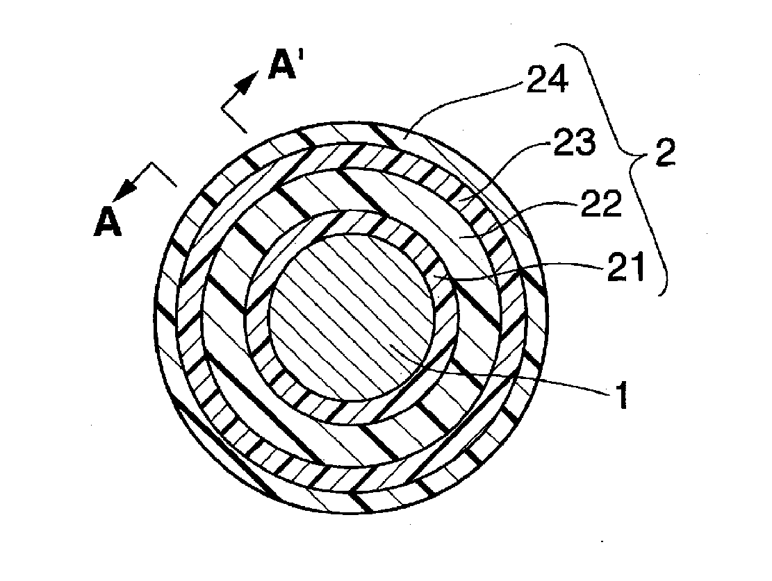
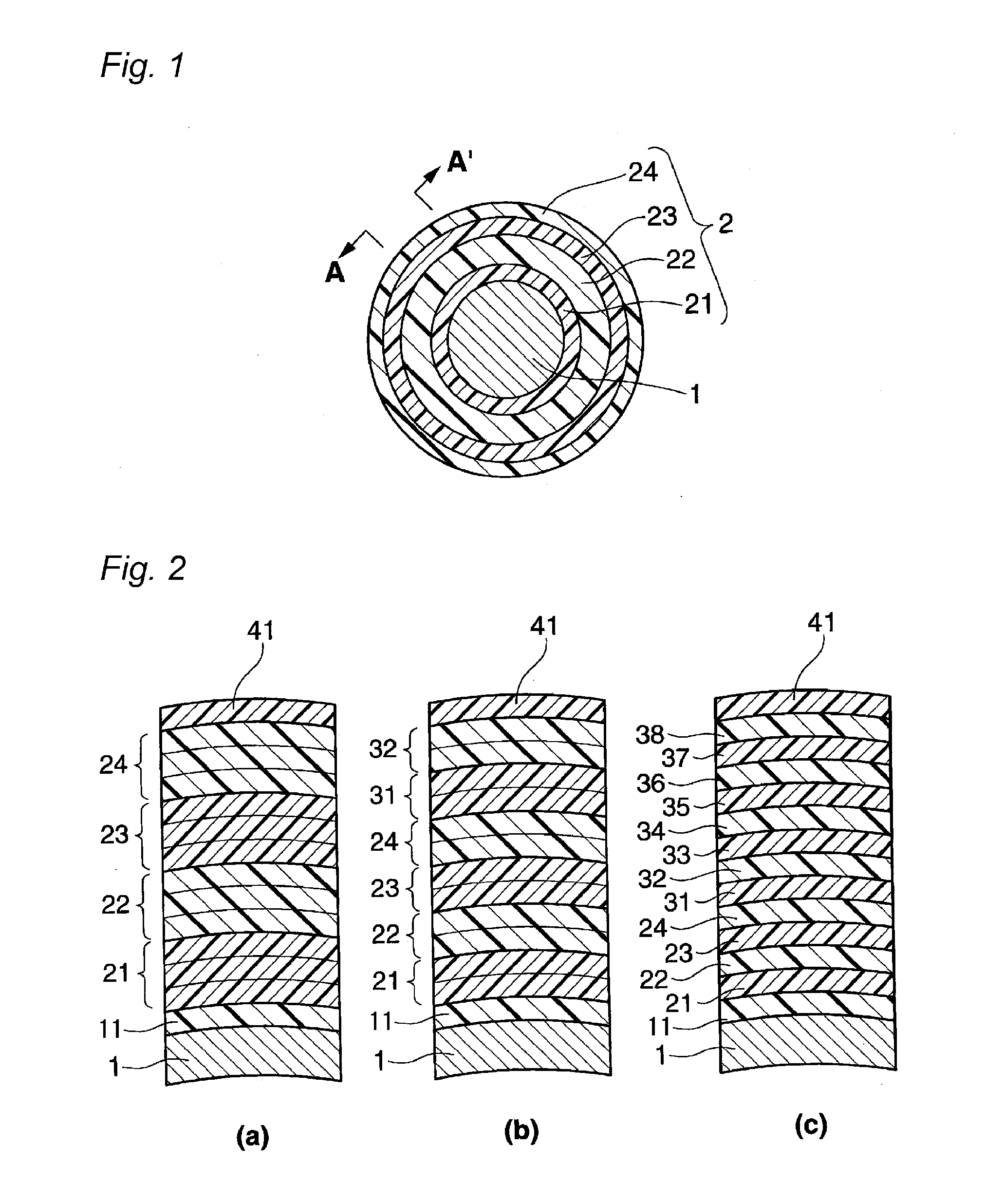
[0056]The inventors of the present invention produced insulated wires having the structures shown in Tables 1 to 4, and evaluated the characteristics and properties of the insulated wires. The insulated wires of Examples 1 to 13 and Comparative Examples 1 to 4 were each obtained, by alternately laminating the insulating layer low in a dielectric constant and the insulating layer high in a dielectric constant, as shown in Tables 1 to 4, on a copper conductor with diameter 1 mm, in the number of repetitions shown in Tables 1 to 4, to thereby form the insulating layers with the respective thickness shown in Tables 1 to 4. Herein, in Examples 1 to 10, Example 13, and Comparative Example 3, the insulated wires produced had an adherent polyamideimide layer composed of HI-406 series (manufactured by Hitachi Chemical Co., Ltd., trade name) around ...


PUM

PropertyMeasurementUnit
frequencyaaaaaaaaaa
glass transition temperatureaaaaaaaaaa
temperatureaaaaaaaaaa

Abstract

{Problems} To provide an insulated wire, which is high in a dielectric breakdown resistance even if insulating resin coatings are laminated, because the interlayer adhesiveness is excellent, and which is excellent in a partial discharge resistance, because the dielectric constant is low.{Means to solve} An insulated wire, having directly or indirectly on a conductor (1), at least two laminate units each formed by laminating an insulating layer (21,23) and an insulating layer (22, 24) higher in a dielectric constant than the insulating layer (21, 23), in this order from the conductor side.

Description

TECHNICAL FIELD[0001]The present invention relates to an insulated wire.BACKGROUND ART[0002]Inverters have become installed in many types of electrical equipments, as efficient variable-speed control units. However, inverters are switched at a frequency of several kHz to several ten kHz, to cause a surge voltage at every pulse thereof. Such an inverter surge is a phenomenon in which reflection occurs at a breakpoint of impedance, for example, at a starting end, a termination end, or the like of a connected wire in the propagation system, and consequently, to apply a voltage twice as high as the inverter output voltage at the maximum. In particular, an output pulse occurred due to a high-speed switching device, such as an IGBT, is high in steep voltage rise. Accordingly, even if a connection cable is short, the surge voltage is high, and voltage decay due to the connection cable is also low. As a result, a voltage almost twice as high as the inverter output voltage occurs.[0003]As co...

Claims


Application Information

Patent Timeline
Patent Type & Authority Applications(United States)
IPC IPC(8): H01B7/00
CPCH01B3/306H01B7/0208H01B3/427H01B7/00H01B7/02
Inventor OYA, MAKOTOMUTO, DAISUKE
Owner FURUKAWA ELECTRIC CO LTD
Why Eureka
Try Eureka