
Separation Process

a technology of separation process and gas bubble, which is applied in the direction of separation process, electromechanical device, water/sludge/sewage treatment, etc., can solve the problems of avoiding the requirement, increasing the probability of oil droplets and contaminants from the water stream to be removed, and avoiding significant cost and downtime. , the probability of gas bubbles rising, the effect of increasing the number of gas bubbles

Inactive Publication Date: 2012-11-15
PROCESS GROUP
View PDF11 Cites 7 Cited by
  • Summary
  • Abstract
  • Description
  • Claims
  • Application Information

AI Technical Summary

Benefits of technology

[0024]Without wishing to be limited to any one theory, it should be appreciated that smaller bubbles generally provide a better recovery of contaminants dispersed within waste water streams in flotation. This is largely related to the bubble diameter being proportional to its vertical rising velocity. For waste water containing oil droplets and related contaminants, the oil droplets and contaminants generally have an average diameter of less than 40 micron. This size is similar to the average size of a large proportion of the gas bubbles created by the electrolytic process of the present invention. This size similarity provides an increased probability of coalescence of the bubbles, oil droplets and contaminants, resulting in increased probability of removal of the oil droplets and contaminants from the water stream.
[0025]A bubble generator according to the present invention therefore provides an alternate means of producing a dispersion of fine gas bubbles in a water stream that can be used in a flotation vessel to provide a good recovery rate of contaminants in waste water including contaminants contained within the flotation vessel.
[0029]In an alternate embodiment, inert electrodes are used in the bubble generator. Inert electrode material is selected to be conductive to electric current flow, but not sacrificial during the electrolysis process. This generally avoids the need to regularly replace the electrodes, thereby avoiding significant cost and down-time in a continuous separation process. Additionally, the use of inert electrodes avoids the production of undesirable metal ions or metal hydroxides within the waste water. Suitable inert electrodes include at least one of titanium, stainless steel, platinum or duriron optionally coated with at least one of lead dioxide, platinum, or ruthenium oxide. In one embodiment, the anode comprises titanium coated with ruthenium oxide and the cathode comprises stainless steel. In another embodiment, the cathode comprises carbon and the anode comprises duriron. As can be appreciated, duriron is a cast alloy having the following nominal composition: silicon ˜14.2 wt. %, carbon ˜0.8 wt. %, balance iron.
[0040]In other embodiments, the bubble generator is fed substantially the same waste water that is fed into the flotation vessel. In such embodiments, both the inlet of the bubble generator and an inlet of the flotation vessel can be in fluid communication with a waste water inlet conduit, the ratio of waste water fed to the bubble generator as compared to the flotation vessel being controlled to enhance the separation of contaminants in the flotation vessel.
[0054]The water stream fed into the bubble generator can be sourced from a variety of water sources. In one embodiment, the process further includes the step of feeding at least a portion of the treated water from the flotation vessel into the bubble generator. In another embodiment, the process further includes the step of feeding a first portion of the waste water stream into the flotation vessel and a second portion of the waste water stream into the bubble generator, the ratio of waste water fed to the bubble generator as compared to the flotation vessel being controlled to enhance the separation of contaminants in the flotation vessel.

Problems solved by technology

Significantly, the use of electrolysis negates the requirement of prior arrangements using pumps and eductors for injecting gas into the waste water, and the associated (prior mentioned) disadvantages of these types of arrangements.
This size similarity provides an increased probability of coalescence of the bubbles, oil droplets and contaminants, resulting in increased probability of removal of the oil droplets and contaminants from the water stream.

Method used


Image

  • Separation Process
  • Separation Process
  • Separation Process

Examples


Embodiment Construction

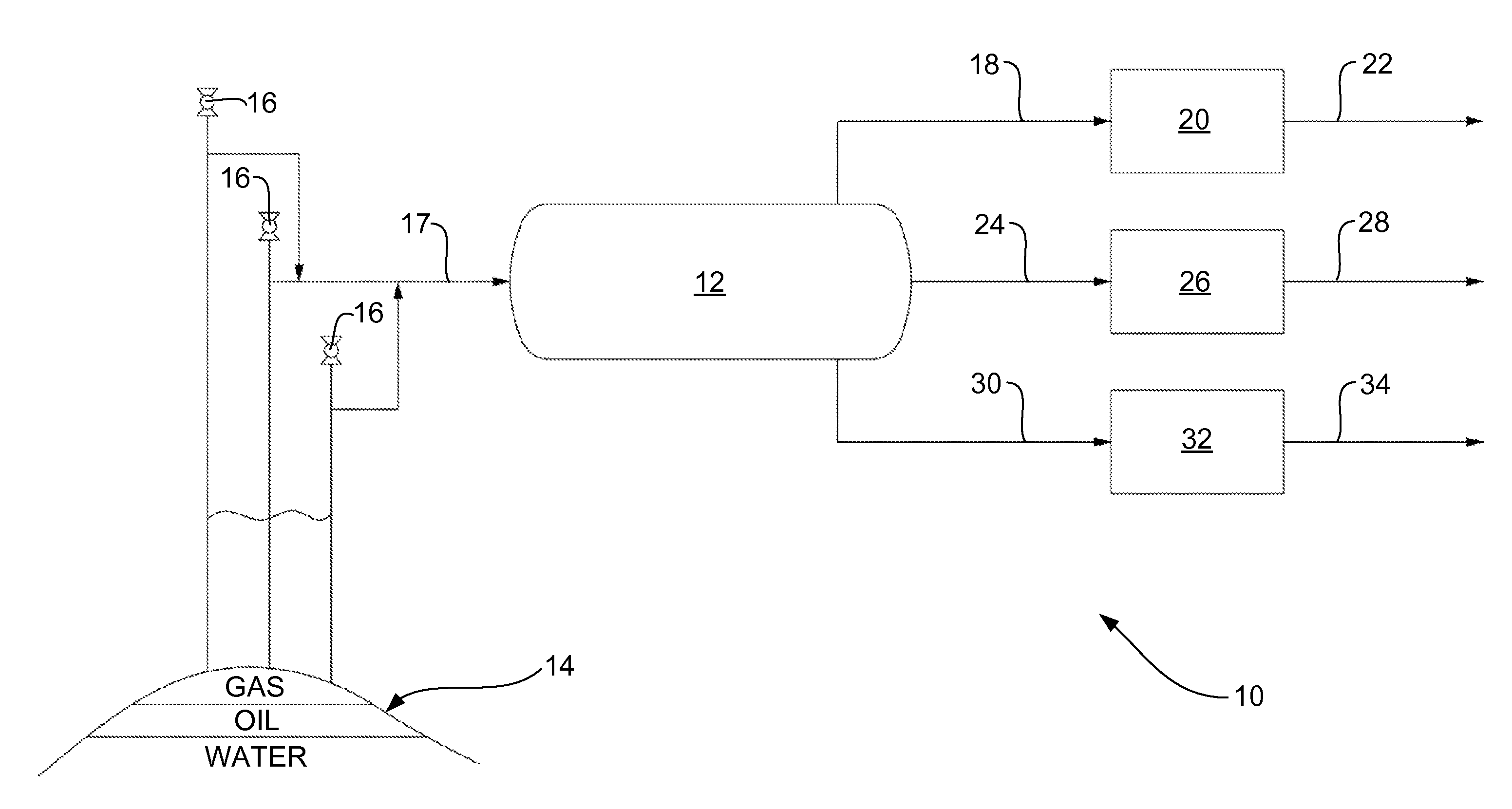
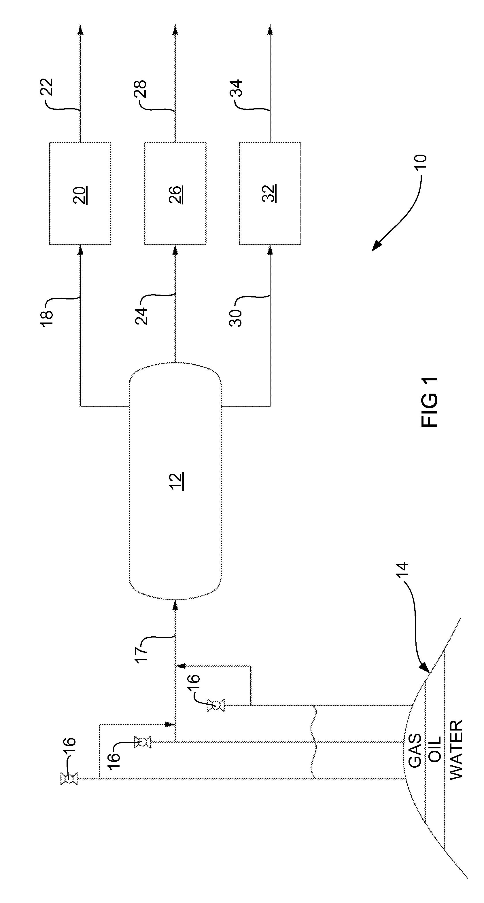
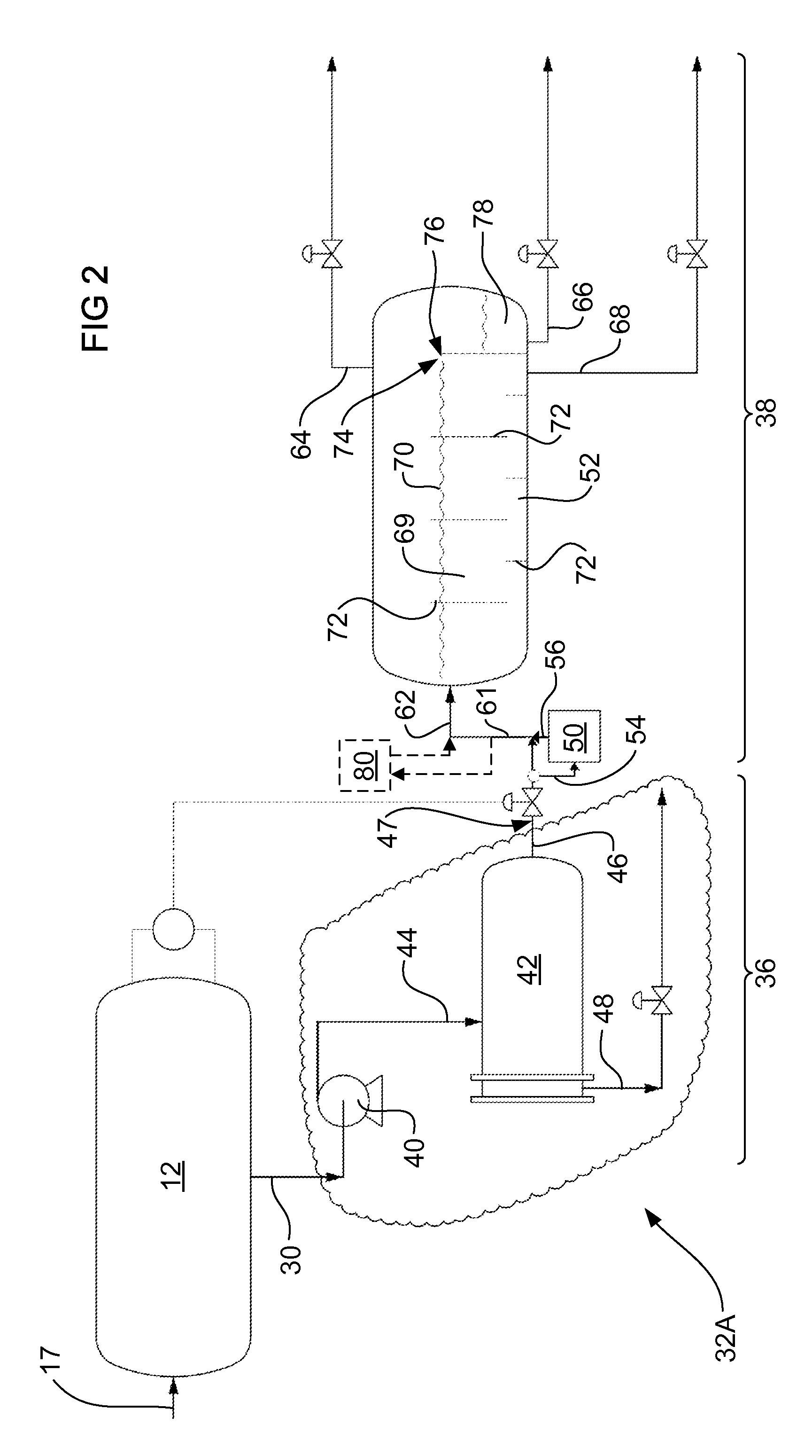
[0061]FIGS. 1 to 4 illustrate a treatment process for produced water resulting from a production separator 12 used in a first separation stage 10 in the course of oil and / or gas production in the petroleum industry.

[0062]Referring to FIG. 1, there is shown a basic flow diagram providing the general flow paths of materials in the first separation stage 10 of a well head product extracted from an oil / gas well 16. Preceding the first separation stage 10, a well head oil product is extracted from an oil and / or gas reservoir 14 via an oil / gas well 16. The well head product typically comprises a mix of oil, gas, water and other contaminants. The well head product is fed from the oil / gas wells 16 to the production separator 12 through inlet stream 17 to undergo the first separation stage 10.

[0063]The illustrated production separator 12 is a large tank held at or above atmospheric pressure. The well head product is fed into the production separator 12 and allowed to settle for a settling pe...


PUM

PropertyMeasurementUnit
diameteraaaaaaaaaa
diameteraaaaaaaaaa
diameteraaaaaaaaaa

Abstract

A bubble generator for generating gas bubbles for a flotation vessel, the bubble generator including at least one inlet through which a water stream can enter the bubble generator; at least one pair of electrodes capable of electrically decomposing water to create gas bubbles; and at least one outlet through which water entrained with gas bubbles can exit the bubble generator. In use, at least one of the outlets is in fluid communication with a flotation vessel containing waste water including contaminants, the gas bubbles being used to separate at least a portion of the contaminants from the waste water in the flotation vessel.

Description

BACKGROUND OF THE INVENTION[0001]1. Field of the Invention[0002]The present invention generally relates to a separation process, a bubble generator for use in the separation process and a flotation separator. The invention is particularly applicable for reducing the oil-content of “produced water” using a flotation technique and it will be convenient to hereinafter disclose the invention in relation to that exemplary application. However, it should be appreciated that the invention is not limited to that application and could be used to separate various other types of waste water or contaminated water flows.[0003]2. Description of the Prior Art[0004]Water is present in most oil and gas reservoirs. The product extracted from an oil and gas reservoir (“the well head product”) therefore contains a water component that needs to be separated from the oil and gas component to produce a commercially acceptable oil product and gas product. This separation process is typically conducted usin...

Claims


Application Information

Patent Timeline
Patent Type & Authority Applications(United States)
IPC IPC(8): C02F1/465C25B11/02C25B11/04C25B9/00C25B11/10
CPCC25B1/04B01D17/0205B01D17/0214Y02E60/366C02F1/40C02F1/465C02F2103/10B01D19/00Y02E60/36
Inventor TUCKETT, PHILIPDREHER, TRINA MARGARET
Owner PROCESS GROUP
Learn More